Table of Contents
Advertisement
CONTENTS
PRECAUTIONS ............................................................. 4
INTRODUCTION ........................................................... 6
FEATURES .................................................................... 6
TECHNICAL SPECIFICATION ....................................... 7
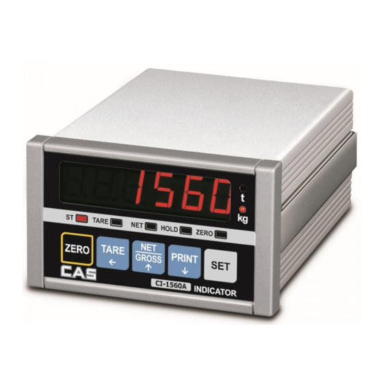
MEASURE OF APPEARANCE ...................................... 8
FRONT PANEL ............................................................. 9
REAR PANEL ............................................................... 10
INSTALLATION & CONNECTION ................................. 11
TEST MODE ................................................................. 13
CALIBRATION MODE ................................................... 16
SET MODE ................................................................... 20
WEIGHING MODE ........................................................ 28
RS-232C INTERFACE/CLOCK ...................................... 32
ERROR MESSAGE AND TROUBLE SHOOTING .......... 36
38
Advertisement
Table of Contents

Related Manuals for CAS 1560A


Summary of Contents for CAS 1560A
-
Page 1: Table Of Contents
CONTENTS PRECAUTIONS ............. 4 INTRODUCTION ............6 FEATURES ..............6 TECHNICAL SPECIFICATION ........7 MEASURE OF APPEARANCE ........8 FRONT PANEL ............. 9 REAR PANEL ............... 10 INSTALLATION & CONNECTION ......... 11 TEST MODE ..............13 CALIBRATION MODE ........... 16 SET MODE .............. -
Page 2: Precautions
PRECATUTIONS Place the indicator on a flat and stable Do not subject the scale to sudden Do not use inflammable materials in surface. temperature changes. cleaning This scale must be installed in a dry and Do not severely press because the light Keep the scale away from strong EMI noises may cause incorrect weight reading liquid free environment. -
Page 3: Introduction
INTRODUCTION TECHNICAL SPECIFICATION We greatly appreciate your purchase of the CI-1500 weighing indicator. These goods Analog Part & A/D Conversion perform excellently and exhibit splendid properties through strike tests. CAS indicator Load cell Excitation Voltage DC 5V (CI-series) is delicately designed to coincide with the special requirements of several industrial fields and includes many functions and various external interfaces. -
Page 4: Measure Of Appearance
GENERAL SPECIFICATION FRONT PANEL Power AC 220V, 50/60 Hz Size 110(W) x 130(D) x 66(H) Temperature -10 ℃ ~+40 ℃ Weight Approx 750g Power Consumption Approx 10W MEASURE OF APPEARANCE 1. Weight display Lamp n ST Lamp : turn on when the weight is stable. n TARE Lamp : turn on when tare weight is stored. -
Page 5: Rear Panel
REAR PANEL INSTALLATION & CONNECTION Load cell connection Pin1: Excitation voltage+ Pin2: Excitation voltage- Pin3: Sense voltage+ Pin4: Sense voltage- Pin5: Shield n Connecting method Each L/C manufacturer’s or model’s wire color could be different. In that case, please note the following n INPUT : External input diagram. -
Page 6: Test Mode
n Resolution to load cell output rate TEST MODE 10V impression to load cell Max. Recommended resolution load cell output n How to enter 2 mV 1/1,000(Max) Turn on the power while pressing the ZERO key on the front of the indicator. 4 mV 1/2,000(Max) When test is done, Press SET key. - Page 7 Note 5. The test output format of printer is as the follows. TEST 4 n FUNCTION : RS-232 test with computer (SERIAL port) ----------------- DISPLAY DESCRIPTION CI-1500A http://www.cas.co.kr Waiting for transmission and reception TEST OK SET : to next menu ----------------- Transmitted : none, Received : 1...
-
Page 8: Calibration Mode
TEST 6 (CI-1560A) 3. Calibration Menu (CAL 1- CAL 7) n FUNCTION : External input/output (relay test) CAL 1 : Maximum Capacity Set CAL 2 : Minimum Division Set DISPLAY DESCRIPTION CAL 3 : Setting Weight in Span Calibration SET : Move to next Waiting for key and External input CAL 4 : Zero Calibration menu... - Page 9 CAL 3 CAL 5 n FUNCTION : Setting Weight In Span Calibration n FUNCTION : Span Calibration RANGE 1~Maximum capacity of CAL 1 DISPLAY DESCRIPTION DISPLAY DESCRIPTION CAL 5 condition CAL 3 condition CAL 5 SET key : store and CAL 3 Load the weight which was set in move into next menu...
-
Page 10: Set Mode
SET MODE Function Display Description F02 0 is Hold key SET key usage(0~2) F02 1 is Total data print 1. How to enter Turn on the power while pressing the TARE key on the front of the indicator. F02 2 is Start key in relay mode 2. - Page 11 Function Display Description Function Display Description F07 0 weight backup is off F11 0 600bps(bit per second) Weight backup (OFF, ON) F11 1 1200bps F07 1 weght backup is on Baud rate Note 1. In case occurring sudden power failure, it can be memoried the moment F11 2 2400bps (Unit of speed In...
- Page 12 ※ When you select 1 of F14. ※ You can set Lo, H - FALL, L - FALL value same as above. n HI, Lo, H - FALL, L - FALL Function Display Description Function Display Description C1 99 Year : 1999 Set Year (00~99) Set Hi, Lo, H - FALL, 100 kg...
- Page 13 n Limit Mode n Limit Type Checker Mode WEIGHT WEIGHT (LOW limit) (HIGH limit) (LOW limit) (HIGH limit) RELAY RELAY 0 kg 50 kg 100 kg 0 kg 50 kg 100 kg ZERO ZERO (OUT RELAY 1) (OUT RELAY 1) (OUT RELAY 2) (OUT RELAY 2) HIGH...
-
Page 14: Weighing Mode
n Example 2. Tare Function Usage WEIGHING MODE Display or Key On platform Description 1.How to enter step 1 Contaiiner Tare weight : 200kg Turn ON/OFF switch on and you will enter the WEIGHING Mode. Store current weight as the TARE step 2 2. - Page 15 n Example 3. To display NET or GROSS weight. Note 1. Choose HOLD type in SET menu (F13) Average HOLD(F13 0): Compute the average weight of oscillating weights. Display or Key On platform Description Peak HOLD(F13 1) : Choose the maximum weight among oscillating Article weight : 10.00kg weights.
-
Page 16: Rs-232C Interface/Clock
※ Simple communication program (C) RS-232C INTERFACE/CLOCK #include <bios.h> #include <conio.h> Transmit mode : RS-232C interface #define COM1 Baud rate 600, 1200, 2400, 4800, 9600, 19200 #define DATA_READY 0x100 Output mode stable, Unstable, Data is required #define TRUE #define FALSE n Type : EIA - RS - 232C n Method : Full-duplex, asynchronous transmission Fomat #define SETTINGS ( 0x80 | 0x03 | 0x00 | 0x00) - Page 17 CAS TOP printer connection (P-202) RS- 232C Port Connection n RS 232C port connection to PC RXD 3 ㅇ ㅇ 9 Transmit Data Connect SERIAL port on the rear panel of the indicator to serial port of PC as the TXD 2 ㅇ...
-
Page 18: Error Message And Trouble Shooting
ERR 24 ERROR MESSAGE & TROUBLE SHOOTING n Reason Load Cell output Volltage is too low at span Calibration. (1) In Weighing Mode ERR 25 ERR 02 n Reason n Reason Load Cell output Volltage is too high at span Calibration. Load cell connection failure or error in A/D conversion part.
Need help?
Do you have a question about the 1560A and is the answer not in the manual?
Questions and answers