
Related Manuals for Magnetek Flex 8EX2


Summarization of Contents
SERVICE INFORMATION
U.S. Service Information
Contact information for service and technical support in the United States.
World Headquarters
Address and contact details for Magnetek's global headquarters.
Canada Service Information
Contact details for service and technical support in Canada.
EU Market Contact
Contact person and address for the European market.
PRODUCT MANUAL SAFETY INFORMATION
WARRANTY INFORMATION
Information regarding product warranties is available on the Magnetek website.
1 Introduction
List of notable features
Overview of key features and capabilities of the Flex EX2 radio remote control system.
2 Radio Controlled Safety
WARNINGS and CAUTIONS
Explains the meaning and importance of WARNING and CAUTION statements in the manual.
2.1 Critical Installation Considerations
Essential safety guidelines to follow before installing and operating the equipment.
2.2 General
General safety advice for operating material handling equipment, emphasizing operator caution.
2.3 Persons Authorized to Operate Radio Controlled Cranes
Specifies that only trained and authorized personnel should operate radio-controlled equipment.
2.4 Safety Information and Recommended Training for Radio Controlled Equipment Operators
Details required knowledge and skills for operators, and actions they should and should not perform.
2.5 Transmitter Unit
Guidelines for the proper use, storage, and handling of the transmitter unit.
2.6 Pre-Operation Test
Steps to perform before starting operations to ensure the system is safe and functional.
2.7 Batteries
Safety warnings related to battery handling, charging, and disposal procedures.
3 General System Information
3.1 RS System Types
Illustrates different configurations of the RS system with associated crane/hoist setups.
3.2 Transmitter
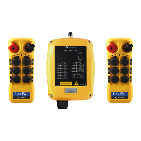
3.2.1 External Illustration (8EX2)
Diagram showing the external components of the 8-button transmitter.
3.2.2 External Illustration (12EX2)
Diagram showing the external components of the 12-button transmitter.
3.2.3 Internal Illustration (8EX2)
Diagram showing the internal components of the 8-button transmitter.
3.2.4 Internal Illustration (12EX2)
Diagram showing the internal components of the 12-button transmitter.
3.3 Receiver
3.3.1 External Illustration
Diagram showing the external components of the receiver unit.
3.3.2 Internal Illustration
Diagram showing the internal components of the receiver unit.
4 Function Settings
4.1 Transmitter
Configuration options and settings for the transmitter unit.
4.2 Receiver
Configuration options and settings for the receiver unit.
4.1 Transmitter
4.1.1 Transmitter Firmware Version
Procedure to check the firmware version of the transmitter.
4.1.2 Display Frequency Band
Procedure to display the current operating frequency band of the transmitter.
4.1.3 Transmitter Channel Settings – Assigned Channel Scheme
How to set or verify the transmitter's assigned channel for system communication.
4.1.4 Remote Pairing
Instructions for pairing transmitters with each other or with receivers wirelessly.
4.1.5 Transmitter Output Power Settings
Information on transmitter output power settings and FCC compliance.
4.1.6 Transmitter Inactivity Timer Settings
Configuration of the inactivity timer that puts the transmitter into sleep mode.
4.1.7 Zero-G Sensor Settings
Description of the Zero-G sensor feature for preventing unintended operation.
4.1.8 Transmitter Start Function Settings
Settings that determine how the transmitter reactivates the system from sleep mode.
4.1.9 Infrared Transmitter Settings
Overview of settings configurable via the IR programmer unit.
4.1.10 I-Chip
Information about using an I-Chip for data transfer and compatibility.
4.2 Receiver
4.2.1 Receiver Channel Settings
Procedure to set the receiver's operating channel using dipswitches.
4.2.2 Receiver Channel Scanning Function
Explanation of the receiver's channel scanning capability for finding active channels.
4.2.3 Dipswitch Settings
Details on various dipswitch configurations and their functions for the receiver.
4.2.4 Jumper Settings
Explanation of jumper settings for receiver functions like system testing and pairing.
4.2.5 Infrared Receiver Settings
Overview of settings configurable via the IR programmer unit for receivers.
4.2.6 Fuse Ratings
Table listing fuse types and their corresponding current ratings for different voltage inputs.
4.2.7 System Channels Table
Table mapping dipswitch settings to primary and secondary channel frequencies.
5 Receiver Installation
5.1 Output Relay Contact Diagrams
Diagrams illustrating the output relay contact configurations for the Flex 4EX2.
5.2 Pre-installation Precautions
Essential safety and system checks to perform before installing the receiver.
5.3 Step-by-Step Installation
Detailed instructions for mounting and installing the receiver unit.
6 Operating Procedures
6.1 General Operation
Step-by-step guide for powering on, operating, and shutting down the radio control system.
6.2 Changing Batteries
Instructions for replacing the batteries in the transmitter unit.
6.3 Battery Charging
Information on charging the rechargeable batteries used with the transmitter.
6.4 System Status Light Indications
Explanation of status light indicators on both transmitter and receiver units.
6.4 System Status Light Indications
6.4.1 Transmitter Status Indications
Table detailing transmitter status light patterns and their meanings.
6.4.2 Receiver Status Indications
Table detailing receiver status light patterns and their meanings.
6.4.3 Receiver Power Indications
Table indicating receiver power status based on its LED.
6.4.4 Receiver COM Indications
Table indicating receiver communication status with the relay board.
Need help?
Do you have a question about the Flex 8EX2 and is the answer not in the manual?
Questions and answers