
Related Manuals for Magnetek Mini-MBT Transmitter Engineered


Summary of Contents for Magnetek Mini-MBT Transmitter Engineered
- Page 1 Mini-MBT Transmitter Engineered Radio Remote Control Part Number: 198-80203-0002 R1 June 2015 © 2015 Magnetek Material Handling...
- Page 2 ® brand Mini-MBT Transmitter Radio Remote Equipment Control. Magnetek has set a whole new standard in radio-remote performance, dependability, and value with this line of modular receivers. If your product ever needs modification or service, please contact one of our representatives at the following locations: U.S.
-
Page 3: Table Of Contents
TABLE OF CONTENTS PRODUCT MANUAL SAFETY INFORMATION ................5 PRODUCT WARRANTY INFORMATION ..................5 CRITICAL INSTALLATION CONSIDERATIONS ................7 GENERAL ............................. 7 PERSONS AUTHORIZED TO OPERATE RADIO CONTROLLED EQUIPMENT ....... 7 SAFEY INFORMATION AND RECOMMENDED TRAINING FOR RADIO CONTROLLED EQUIPMENT OPERATORS ........................7 TRANSMITTER UNIT ........................ - Page 4 OPTIONAL PROGRAMMING WITH RCP ..................24 ACCESS CODES ........................24 CHANGING RECIEVER ACCESS CODES ................25 CONNECTING THE MINI-MBT TO A COMPUTER ..............25 CONFIGURATION WITH RCP ....................26 TRANSMITTER CHANNEL CONFIGURATION SETTINGS ............27 FCC STATEMENTS ........................27 433MHz CHANNEL SET ......................28 433 MHz TELEMOTIVE LEGACY CHANNEL SET: TMS AND TDMA ........
-
Page 5: Product Manual Safety Information
Magnetek Products to know, understand and follow all of these requirements. It is the responsibility of the owner of the Magnetek Products to make its employees aware of all of the above listed requirements and to make certain that all operators are properly trained. No one should use Magnetek Products prior to becoming familiar with and being trained in these requirements. - Page 6 WARNINGS and CAUTIONS Throughout this document WARNING and CAUTION statements have been deliberately placed to highlight items critical to the protection of personnel and equipment. WARNING – A warning highlights an essential operating or maintenance procedure, practice, etc. which if not strictly observed, could result in injury or death of personnel, or long term physical hazards.
-
Page 7: Critical Installation Considerations
2. CRITICAL INSTALLATION CONSIDERATIONS WARNING PRIOR TO INSTALLATION AND OPERATION OF THIS EQUIPMENT, READ AND DEVELOP AN UNDERSTANDING OF THE CONTENTS OF THIS MANUAL AND THE OPERATION MANUAL OF THE EQUIPMENT OR DEVICE TO WHICH THIS EQUIPMENT WILL BE INTERFACED. FAILURE TO FOLLOW THIS WARNING COULD RESULT IN SERIOUS INJURY OR DEATH AND DAMAGE TO EQUIPMENT. - Page 8 PERFORMANCE OR SAFETY CONCERNS ARE OBSERVED, THE EQUIPMENT SHOULD IMMEDIATELY BE TAKEN OUT OF SERVICE AND BE REPORTED TO THE SUPERVISOR. DAMAGED AND INOPERABLE RADIO CONTROLLER EQUIPMENT SHOULD BE RETURNED TO MAGNETEK FOR EVALUATION AND REPAIR. FAILURE TO FOLLOW THIS WARNING COULD RESULT IN SERIOUS INJURY OR DEATH AND DAMAGE TO EQUIPMENT.
-
Page 9: Transmitter Unit
FAILURE TO FOLLOW THIS WARNING COULD RESULT IN SERIOUS INJURY OR DEATH AND DAMAGE TO EQUIPMENT. Use only batteries approved by Magnetek for the specific product. Do not dispose of a battery pack in fire; it may explode. Do not attempt to open the battery pack. -
Page 10: Battery Disposal
Do not short the charger. Do not attempt to charge a damaged battery. Use only Magnetek approved chargers for the appropriate battery pack. Do not attempt to use a battery that is leaking, swollen or corroded. Charger units are not intended for outdoor use. Only use charger units indoors. - Page 11 use the crane, hoist or lifting device to lift, support or transport people lift or carry any loads over people operate the crane, hoist or lifting device unless all persons, including the operator, are and remain clear of the supported load and any potential pinch points operate a crane, hoist or lifting device when the device is not centered over the load operate a crane, hoist or lifting device if the chain or wire rope is not seated properly in the sprockets, drum or sheave...
-
Page 12: Mini-Mbt Standard Configuration And Operation
3. MINI-MBT STANDARD CONFIGURATION AND OPERATION WARNING BEFORE OPERATING THE TRANSMITTER, FAMILIARIZE YOURSELF WITH ALL SAFETY INFORMATION IN THIS MANUAL, CORRESPONDING RECEIVER SYSTEM MANUAL, APPROPRIATE MANUAL SUPPLEMENTS AND ANY OTHER LOCAL, STATE, OR FEDERAL RULES OR REGULATIONS ALREADY IN EXISTENCE. FAILURE TO FOLLOW THIS WARNING COULD RESULT IN SERIOUS INJURY OR DEATH AND DAMAGE TO EQUIPMENT. -
Page 13: Installing The Battery Pack
INSTALLING THE BATTERY PACK Prior to utilizing the Mini-MBT transmitter, the battery pack must be installed. 3.1.1 Alkaline Battery Pack (BT151-0) The Mini-MBT comes standard with a battery pack (BT151-0) that holds four disposable AA alkaline batteries. Figure 2: BT151-0 Battery Pack To change the alkaline batteries in the battery pack, unscrew the four screws holding the battery pack in the transmitter. -
Page 14: Optional Nimh Rechargeable Battery Pack (Bt150-0)
3.1.2 Optional NiMH Rechargeable Battery Pack (BT150-0) The rechargeable battery pack BT150-0 is a sealed pack that has no user-serviceable components within Figure 4: BT150-0 Battery Pack The rechargeable battery pack BT150-0 is shipped from the factory with a minimal charge and will need to be charged prior to use for the first time with the specified charger. -
Page 15: Machine Stop And Start Push Button
3.2.1 Machine Stop and START Push Button 1. Ensure the Machine Stop is in the raised (pulled out) position. 2. After the unit has initialized (refer to Sections 3.2.4 and 3.2.5 for initialization), press the START push button to enable communication with the receiver. 3.2.2 Machine Stop and ON-OFF-START Toggle 1. -
Page 16: Transmitter Initialization (With Optional Graphic User Interface Screen)
3.2.5 Transmitter Initialization (with Optional Graphic User Interface Screen) Upon turning the transmitter on, the LCD screen turns on and the unit will perform a routine initialization. During initialization, the Mini-MBT scans for any switches or motions that may be on during power up. If any switches or motions are on, the failure will be shown on the display, and the Mini-MBT will power itself down. -
Page 17: Normal Operating Mode With Standard Leds
NORMAL OPERATING MODE WITH STANDARD LEDS 3.6.1 Watch Dog Indicator (Steady Blinking Status LED) The blinking LED represents the watch dog timer within the CPU of the unit. NOTE: The LED should be continuously blinking at all times. If the LED is not blinking the transmitter will need to be rebooted to operate properly. -
Page 18: Command Confirmation
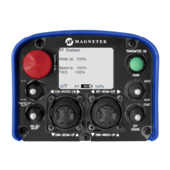
3.7.2 Command Confirmation Each time the user operates a control on the transmitter, a message will be displayed on the graphic user interface screen confirming what is being operated. 3.7.3 Battery Life Indicator Remaining battery life is displayed on the bottom of the graphic user interface screen. Battery life is displayed in 10% increments. -
Page 19: Transmitter Setup
4. TRANSMITTER SETUP The transmitter may have settings changed one of three ways. The RF channel and access code can be programmed using the IR configuration link with a compatible receiver. All other settings can only be changed at the factory or with the optional RCP software. For units with the optional graphic user interface, the Setup Mode can be used to edit configuration settings such as: Access Code, Channel Select, User Code, Transmitter Time Out, Backlight Time Out, Password Enable, Change Password, and more. -
Page 20: Using The Transmitter In Setup Mode (With Optional Graphic User Interface)
If the link is unsuccessful with a compatible receiver, the Status/Battery LED will continue to blink. To cancel the IR configuration receiver without a successful link, move the OFF-ON-START toggle to the OFF position. USING THE TRANSMITTER IN SETUP MODE (WITH OPTIONAL GRAPHIC USER INTERFACE) NOTE: The Setup Mode is only accessed on transmitters equipped with the optional graphic user interface. -
Page 21: Enrange Mini-Mbt Instruction Manual June
The Access Code is a 20-bit binary value with a decimal equivalent of 0 - 1048575. It will be displayed as binary or decimal depending on the application. 4.2.2.2 Channel Select The Channel Select setting determines the frequency that the Mini-MBT is operating on. The user can select channels which correspond to the frequencies in Section 6. - Page 22 When the disabled setting is selected the user will go directly into Setup Mode without being prompted to enter a password. Magnetek strongly recommends enabling the Setup Mode password setting to prevent unauthorized or accidental changes to parameters. NOTE: The unit is shipped with the password requirement enabled and utilizing the factory default password.
- Page 23 position and release. The graphic user interface will display “Attempting” with a countdown of the time while scanning for the receiver’s IR signal. If the receiver is in range and IR link is made, the message will change to “Success”. The transmitter and receiver should be within one foot of each other to ensure successful exchange of information via IR.
-
Page 24: Optional Programming With Rcp
5. OPTIONAL PROGRAMMING WITH RCP Using the optional RCP software makes programming of the Mini-MBT easier and allows for settings to be saved for future reference. WARNING THE USE OF RCP (RADIO CONTROL PROGRAMMER) IS INTENDED FOR USE BY AUTHORIZED PERSONS ONLY. -
Page 25: Changing Reciever Access Codes
CHANGING RECIEVER ACCESS CODES Receiver Access Code Programming. For detailed instructions on setting parameters including access codes, see the “Programming” section of the applicable receiver manual. WARNING AFTER CHANGING THE ACCESS CODES ON THE TRANSMITTER, TEST THE UNIT BY TURNING IT ON AND OFF NEAR THE APPROPRIATE RECEIVER. -
Page 26: Configuration With Rcp
When plugging in the transmitter to a computer system, the transmitter batteries must be installed. The USB circuit does not provide power to the transmitter. Magnetek highly recommends using a fully charged battery pack when using USB and RCP with the transmitter. -
Page 27: Transmitter Channel Configuration Settings
6. TRANSMITTER CHANNEL CONFIGURATION SETTINGS The RF channel can be set via the setup mode or the optional RCP software on systems equipped with the optional graphic user interface. Sections 6.2 through 6.6 show the channels and protocols available for each transmitter radio frequency option. FCC STATEMENTS Compliance Statement (Part 15.19) This device complies with Part 15 of FCC... -
Page 28: 433Mhz Channel Set
433MHZ CHANNEL SET Channel Frequency 433.000 MHz 433.050 MHz 433.100 MHz 433.150 MHz 433.200 MHz 433.250 MHz 433.300 MHz 433.350 MHz 433.400 MHz 433.450 MHz 433.500 MHz 433.550 MHz 433.600 MHz 433.650 MHz 433.700 MHz 433.750 MHz 433.800 MHz 433.850 MHz 433.900 MHz 433.950 MHz 434.000 MHz... -
Page 29: 433 Mhz Telemotive Legacy Channel Set: Tms And Tdma
433 MHZ TELEMOTIVE LEGACY CHANNEL SET: TMS AND TDMA Channel Count Channel Designator Frequency AK01 439.8 MHz AK02 439.6 MHz AK03 439.4 MHz AK04 439.2 MHz AK05 439.0 MHz AK06 438.8 MHz AK07 438.6 MHz AK08 438.4 MHz AK09 438.2 MHz AK10 438.0 MHz AK11... -
Page 30: 419Mhz Channel Set
419MHZ CHANNEL SET Channel Frequency Channel Frequency 418.950 417.500 418.975 417.550 419.000 417.600 419.025 417.650 419.050 417.700 419.075 417.750 419.100 417.800 419.125 417.850 419.150 417.900 419.175 417.950 419.200 418.000 419.250 418.050 419.275 418.100 416.000 418.150 416.050 418.200 416.100 418.250 416.150 418.300 416.200 418.350... -
Page 31: 900 Mhz Channel Set
900 MHZ CHANNEL SET Channel Frequency 903.30 MHz 906.30 MHz 907.80 MHz 909.30 MHz 912.30 MHz 915.30 MHz 919.80 MHz 921.30 MHz 902.30 MHz 904.10 MHz 904.30 MHz 905.10 MHz 905.50 MHz 905.70 MHz 906.60 MHz 908.70 MHz 908.90 MHz 909.10 MHz 910.10 MHz 910.70 MHz... -
Page 32: Optional Can Bus Tether Feature
NOTE: While the tether cable provides power to the transmitter when connected, it will not recharge batteries in the transmitter. To recharge batteries, you must only use the Magnetek approved chargers for the appropriate battery pack. -
Page 33: Can Connector Receptacle Pin-Out Details
CAN CONNECTOR RECEPTACLE PIN-OUT DETAILS The CAN connector receptacle located on the transmitter has specific pin assignments. It is very critical that these pin assignments are matched in the CAN cable assembly. Keyway Figure 9: CAN Connector Pin Out details Enrange Mini-MBT Instruction Manual June 2015 Page 33 of 37... -
Page 34: General Troubleshooting
8. GENERAL TROUBLESHOOTING Problems Possible Reasons Suggestions Replace the batteries and confirm they are installed according to the polarity marking in Batteries are dead or installed the battery pack. Inspect all battery pack backwards; battery holder is Transmitter will not contacts for damage. -
Page 35: Troubleshooting Optional Tether Operation
ASSEMBLY AND REPLACEMENT PARTS If your transmitter ever needs repair, we always recommend that you have Magnetek perform the repair. If you need to refer to a parts list, refer to your transmitter’s drawing that was included in the shipment of your transmitter. -
Page 36: Notes
9. NOTES Enrange Mini-MBT Instruction Manual June 2015 Page 36 of 37... -
Page 37: Eu Declaration Of Conformity
10. EU DECLARATION OF CONFORMITY Enrange Mini-MBT Instruction Manual June 2015 Page 37 of 37... -
Page 38: Technical Specifications
• Approximately 5.00" x 3.38” x 4.33" (127 x 86 x 110 mm) • Power input: 6-36VDC P.O. Box 13615 N49 W13650 Campbell Drive Canada Facility Magnetek (UK) Ltd. www.magnetek.com Milwaukee, WI 53213 Menomonee Falls, WI 53051 4090B Sladeview Crescent Unit, 3 Bedford Business Centre Toll-Free Phone 800.288.8178... - Page 39 • 120 Vac 60 Hz • 240 Vac 50Hz • 12/24 Vdc P.O. Box 13615 N49 W13650 Campbell Drive Canada Facility Magnetek (UK) Ltd. www.magnetek.com Milwaukee, WI 53213 Menomonee Falls, WI 53051 4090B Sladeview Crescent Unit, 3 Bedford Business Centre Toll-Free Phone 800.288.8178...
- Page 40 Mini-MBT with 2 Joysticks, 4 Toggles, Display, Tethered Connection and Tethered Connection P.O. Box 13615 N49 W13650 Campbell Drive Canada Facility Magnetek (UK) Ltd. www.magnetek.com Milwaukee, WI 53213 Menomonee Falls, WI 53051 4090B Sladeview Crescent Unit, 3 Bedford Business Centre Toll-Free Phone 800.288.8178...
- Page 41 Mini-MBT Transmitter Technical Specifications Mini-MBT IR and USB Port Location P.O. Box 13615 N49 W13650 Campbell Drive Canada Facility Magnetek (UK) Ltd. www.magnetek.com Milwaukee, WI 53213 Menomonee Falls, WI 53051 4090B Sladeview Crescent Unit, 3 Bedford Business Centre Toll-Free Phone 800.288.8178 Phone 262.783.3500...
Need help?
Do you have a question about the Mini-MBT Transmitter Engineered and is the answer not in the manual?
Questions and answers