Table of Contents
Advertisement
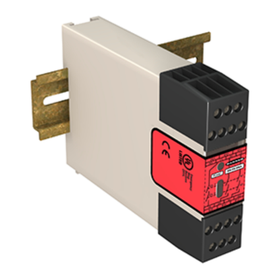
ES-FA-9AA and ES-FA-11AA E-Stop Safety
Module
Instruction Manual
Original Instructions
Models
Models
Supply Voltage
ES-FA-9AA
24 V ac/dc
ES-FA-11AA
WARNING: Not a Stand-Alone Safeguarding Device
This Banner device is not a stand-alone point-of-operation guarding device, as defined by
OSHA regulations. It is necessary to install point-of-operation guarding devices, such as safety light
screens and/or hard guards, to protect personnel from hazardous machinery. Failure to install point-
of-operation guards on hazardous machinery can result in a dangerous condition which could
lead to serious injury or death.
Important: Read this First
The user is responsible for satisfying all local, state, and national laws, rules, codes, and regulations relating to
the use of this product and its application. Banner Engineering Corp. has made every effort to provide complete
application, installation, operation, and maintenance instructions. Please contact a Banner Applications Engineer with any
questions regarding this product.
The user is responsible for making sure that all machine operators, maintenance personnel, electricians, and
supervisors are thoroughly familiar with and understand all instructions regarding the installation, maintenance, and use of
this product, and with the machinery it controls. The user and any personnel involved with the installation and use of this
product must be thoroughly familiar with all applicable standards, some of which are listed within the specifications.
Banner Engineering Corp. makes no claim regarding a specific recommendation of any organization, the accuracy or
effectiveness of any information provided, or the appropriateness of the provided information for a specific application.
Applicable U.S. Standards
ANSI B11 Standards for Machine Tools Safety
Contact: Safety Director, AMT – The Association for Manufacturing Technology, 7901 Westpark Drive, McLean, VA 22102,
Tel.: 703-893-2900
Original Document
60606 Rev. G
•
Monitors emergency stop devices, such as palm buttons and rope/cable pulls,
and positive-opening safety switches used for guard/gate interlocking
•
The safety inputs can monitor:
◦
A +24 V dc source switched by hard/relay contacts in single-channel
hookup, or
◦
Hard/relay contacts in a dual-channel hookup using terminals S11-
S12 and S21-S22
•
The ES-FA-9AA has three normally open output switching channels for
connection to control-reliable power interrupt circuits
•
The ES-FA-11AA has two normally open output switching channels for
connection to control-reliable power interrupt circuits and one normally
closed auxiliary output channel
•
Automatic reset or monitored manual reset
•
Design complies with standards ANSI B11.19, UL991, ISO 13850 (EN418),
and ISO 13849-1 (EN954-1) (Safety Category 4)
•
For use in functional stop category 0 applications per ANSI NFPA 79 and IEC/
EN60204-1
•
6 or 7 amp safety output contacts, depending on model
•
Plug-in terminal blocks
•
24 V ac/dc operation
Outputs
3 Normally Open (NO)
2 Normally Open and 1 Normally Closed (NC)
12 August 2016
Output Contact Rating
6 A
7 A
60606
Advertisement
Table of Contents

Related Manuals for Banner ES-FA-11AA


Summarization of Contents
Original Instructions
Safety Warning: Not a Stand-Alone Safeguarding Device
Device is not a point-of-operation guarding device; requires additional guarding.
Important: Read This First
User responsibility for compliance with laws, codes, regulations, and familiarity with instructions.
Applicable U.S. Standards
Lists U.S. standards relevant to machine tool safety.
Overview
Risk Assessment Warning
Risk assessment is crucial for determining appropriate safety circuit integrity.
Safety Circuit Integrity and ISO 13849-1 Principles
Discusses safety circuit integrity, fault tolerance, and design considerations.
Safety Circuit Integrity Levels
Explains ISO 13849-1 categories (B, 1-4) and US control reliability.
Fault Exclusion
Monitoring of Safety Devices
Details requirements for control reliability and safety category per ISO 13849-1.
Emergency Stop Functions Warning
Do not mute or bypass E-stop devices; function must remain active.
E-Stop and Rope/Cable Pull Switches
Interfacing with positive-opening switches, mounting, and accessibility requirements.
Interlocked Guards (Gates)
Monitoring position of guards/gates using positive-opening switches.
Mechanical Installation
Heat Dissipation Considerations
Ensuring adequate heat dissipation for reliable operation and avoiding overheating.
Electrical Installation
Wiring and connection must be done by qualified personnel adhering to standards.
Electrical Shock Hazard Warning
Disconnect power before any connections or replacements.
Lockout/Tagout Procedures
Guidance on controlling hazardous energy during maintenance.
Safety Input Device Hookup Options
Details single-channel and dual-channel hookup configurations for safety inputs.
Connection of Multiple Switches
Multiple Switching Devices Warning
Never connect switches in parallel; test each device individually.
Connection of Safety Switches
Connection of Reset Switch
Wiring specifications for the reset switch, including voltage and current requirements.
Reset Switch Location Warning
Reset switches must be accessible from outside, in view of, and out of reach of hazardous areas.
Automatic Reset Mode
Configuring the module for automatic reset; requires alternate procedures for safety.
Reset Routine Required Warning
A reset routine is required after clearing a stop condition to prevent unsafe restarts.
Wiring
Machine Control Connection
Generic connection of safety module's output circuits to master stop control elements (MSCs).
External Device Monitoring
Overvoltage Category II and III Installations
Guidelines for installations with applied voltages from 151 V to 250 V ac/dc and overvoltage reduction.
Auxiliary Monitor Contact (ES-FA-11AA)
Use of the auxiliary monitor contact for non-safety-related control functions.
Interfacing MSCs Warning
Avoid intermediate devices that could compromise safety function.
Wiring of Arc Suppressors Warning
Install arc suppressors across actuator coils, never across output contacts.
Initial Checkout Procedures
Checkout Power Disconnect Caution
Always disconnect power to machine control elements before checkout.
Multiple Safety Devices Checkout Warning
Test each safety device individually during checkout to detect faults.
Periodic Checkout Procedure
Repairs and Troubleshooting
Contact Banner Engineering for troubleshooting; no field-replaceable parts.
Module Abuse After Failure Caution
Do not tap or strike a module that will not reset; internal relay may have failed.
Specifications
Details power, output configuration, construction, operating conditions, and certifications.
Need help?
Do you have a question about the ES-FA-11AA and is the answer not in the manual?
Questions and answers