Advertisement
EG24 Precision Edge Sensor Instruction
Manual
Features
Precision edge measurement sensor for web alignment, small part detection, and width measurement.
•
High-resolution measurement ensures material is properly positioned to improve quality and yield
◦
Less than 10-micron resolution precisely monitors edge movement to maximize process
control and reduce wasted material
◦
2 kHz measurement frequency rapidly measures edge location, enabling quick corrections
to material position
•
Wide sensing beam allows for precision measurement over a large area
◦
40-millimeter sensing range measures with the same resolution at any distance, allowing
for edge movement between the sensor face and reflector
◦
24-millimeter wide beam allows for variation in target presentation, which reduces fixturing
complexity and provides more reliable detection than a single-point sensor
•
A selection of measurement modes precisely track edges across a broad variety of moving materials, including a wide range of
opacities and textures
◦
Single Edge for tracking and positioning of web and sheet edges with materials such as foils, films, metals, plastics, or
paper
◦
Width or Gap for confirming quality of a product or in process dimension verification
WARNING:
•
Do not use this device for personnel protection
•
Using this device for personnel protection could result in serious injury or death.
•
This device does not include the self-checking redundant circuitry necessary to allow its use in personnel
safety applications. A device failure or malfunction can cause either an energized (on) or de-energized (off)
output condition.
Models
Family
Beam Width
-
EG
24
-
24 = 24 mm (0.94
EG
in)
Overview
The EG24 can accurately track a target within its 24 mm (0.94 in) wide field of view. It is ideal for tracking the edge of a web or the location or
thickness of a thin target like a thread or wire.
The single-edge and double-edge tracking measurement modes can be configured, depending on the application. Connect the RSD can for
additional configuration options, including other measurement modes.
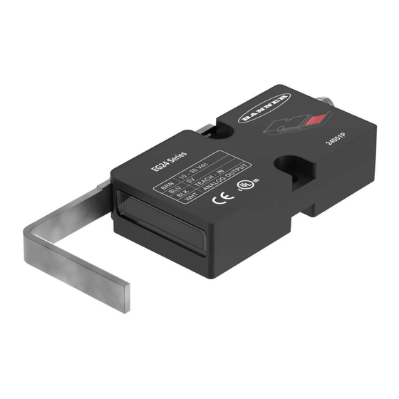
Features and Indicators
3
2
Installation
Attach the retroreflective arm using the two included bolts.
Alternatively, adhere retroreflective tape and mount the EG24 pointing at the retroreflective tape.
Original Instructions
April 02, 2024
Output
I
LVA = Attached Retroreflective
I = 4 mA to 20 mA
LVX = Detached Retroreflective
1
2
3
4
4
1
© Banner Engineering Corp.
Sensing Mode
-
LVA
-
Q7 = Integral 4 pin M8
Feature
Green LED
Amber LED
TEACH button
Connector
Connector
Analog Wire
Q7
B
Blank = white wire
B = Black wire
Description
Power indicator
Output indicator
Mode selection and teach
4-pin, M8
p/n: 239439 Rev. A
Advertisement
Table of Contents

Related Manuals for Banner EG24


Summary of Contents for Banner EG24
- Page 1 Mode selection and teach Connector 4-pin, M8 Installation Attach the retroreflective arm using the two included bolts. Alternatively, adhere retroreflective tape and mount the EG24 pointing at the retroreflective tape. Original Instructions © Banner Engineering Corp. p/n: 239439 Rev. A April 02, 2024...
-
Page 2: Mount The Device
(2) Analog Out bk (4) NOTE: For model EG24-ILVA-Q7B, the analog output is on the black wire (pin 4) and the remote teach is on the white wire (pin 2) Configure the Sensor The default configuration scales the 4 mA to 20 mA output across the full width of the 24 mm (0.94 in) sensing beam. - Page 3 Sets a minimum window, a 4 mA to 20 mA span, centered around that point. To set the field of view, use the following instructions: Put the sensor into TEACH mode. April 02, 2024 page 3 © Banner Engineering Corp. All rights reserved.
- Page 4 Press and hold the TEACH button for two seconds. The LEDs begin flashing and the sensor enters TEACH mode. Remote Input No action is required. If the full field of view is desired, do not use a target for this procedure. If a smaller sensing area than the full field of view is desired, position the edge of the target within the field of view of the EG24. This will be the 4 mA point. Teach the 4 mA position. Method Action Result TEACH Button Press the TEACH button one time.
-
Page 5: Specifications
Power Supply (CE) 0.02 mm Power Consumption, exclusive of load Linearity 0.75 W ± 0.1 mm (0 - 40) mm Output Circuit Measuring Frequency Analog 2000 Hz Output Signal Measuring Distance (to Object) 4 mA to 20 mA < 40 mm April 02, 2024 page 5 © Banner Engineering Corp. All rights reserved. - Page 6 Protection (A) (AWG) (AWG) Certifications Banner Engineering BV Park Lane, Culliganlaan 2F bus 3 1831 Diegem, BELGIUM Turck Banner LTD Blenheim House Blenheim Court Wickford, Essex SS11 8YT GREAT BRITAIN page 6 April 02, 2024 © Banner Engineering Corp. All rights reserved.
- Page 7 All measurements are listed in millimeters [inches], unless noted otherwise. The EG24 can be ordered without the retroreflective arm or the arm can be removed for mounting flexibility. In either case, the provided retroreflective tape must be used and must be mounted 30 mm to 40 mm away from the lens to ensure optimal performance. If a replacement reflector is needed, contact Banner Engineering.
-
Page 8: Banner Engineering Corp Limited Warranty
Banner Engineering Corp Limited Warranty Banner Engineering Corp. warrants its products to be free from defects in material and workmanship for one year following the date of shipment. Banner Engineering Corp. will repair or replace, free of charge, any product of its manufacture which, at the time it is returned to the factory, is found to have been defective during the warranty period. This warranty does not cover damage or liability for misuse, abuse, or the improper application or installation of the Banner product.
Need help?
Do you have a question about the EG24 and is the answer not in the manual?
Questions and answers