
Related Manuals for Woodward easYgen-3400 P2


Summarization of Contents
Brief Overview
General Information
Provides a general overview of the easYgen-3000 Series control units for engine-generator system management applications.
Sample application setup
Illustrates a typical application setup for mains parallel operation with a generator.
Scope of delivery
Fig. 2: Scope of delivery - schematic
Schematic diagram illustrating the components included in the scope of delivery.
Packages
Details the different packages available for the easYgen-3400/3500 controllers and their major differences.
Housing Variants and Hardware Interfaces
Fig. 3: easYgen-3400/3500 P1 Series (housing variants)
Schematic of the easYgen-3400/3500 P1 Series housing variants, labeling different components.
Fig. 4: easYgen-3400-3500 P2 Series (housing variants)
Schematic of the easYgen-3400-3500 P2 Series housing variants, labeling different components.
Application Modes Overview
None
No breaker control. Basic functions include measuring parameters and engine start/stop.
GCBopen
GCB control (open). Includes parameter measurement, engine start/stop, and protection.
GCB
GCB control (open/close). Includes parameter measurement, engine start/stop, protection, and breaker control.
GCB/MCB
GCB/MCB control (open/close). Includes parameter measurement, engine start/stop, protection, and breaker control.
GCB/GGB
GCB/GGB control (open/close). Includes parameter measurement, engine start/stop, protection, and breaker control.
GCB/GGB/MCB
GCB/GGB/MCB control (open/close). Includes parameter measurement, engine start/stop, protection, and breaker control.
GCB/LS5
GCB/LS5 control (open/close). Includes parameter measurement, engine start/stop, protection, and connection to LS-5 system.
GCB/L-MCB
GCB/L-MCB control (open/close). Includes parameter measurement, engine start/stop, protection, and MCB operation via LS-5.
GCB/GGB/L-MCB
GCB/GGB/L-MCB control (open/close). Includes parameter measurement, engine start/stop, protection, GCB/GGB operation, MCB operation via LS-5, and mains failure detection.
GCB/L-GGB
GCB/L-GGB control (open/close). Includes parameter measurement, engine start/stop, protection, and GGB operation via LS-5.
GCB/L-GGB/L-MCB
GCB/L-GGB/L-MCB control (open/close). Includes parameter measurement, engine start/stop, protection, GGB operation via LS-5, MCB operation via LS-5, and mains failure detection.
Installation
3.1 Mount Unit (Sheet Metal Housing)
Provides dimensions and drill plan for mounting the sheet metal housing unit.
3.2 Mount Unit (Plastic Housing)
Details on mounting the unit using clamp fasteners or screw kit, including dimensions and panel cutout.
3.3 Setup Connections
Covers general notes on setup connections, wire sizes, and terminal allocation for different housing types.
3.3.1 Terminal Allocation
Explains the allocation of device terminals for both plastic and sheet metal housings.
3.3.2 Wiring Diagram
Provides wiring diagrams for easYgen-3400 sheet metal housing and general notes regarding PE terminal connection.
3.3.3 Power Supply
Details general notes, warnings, and schematic for connecting the power supply unit.
3.3.4 Charging Alternator
Explains the function of the charging alternator D+ output during engine start-up and regular operation.
3.3.5 Voltage Measuring
Provides general notes on voltage measurement, including warnings about improper setup and recommended fuse ratings.
3.3.5.1 Generator Voltage
Details generator voltage measurement, including parameter settings for different voltage systems and wiring diagrams.
3.3.5.2 Mains Voltage
Details mains voltage measurement, including parameter settings for different voltage systems and wiring diagrams.
3.3.5.3 Busbar Voltage
Provides information on busbar voltage measurement, including general notes and schematic wiring.
3.3.6 Current Measuring
Details current measurement for generator and mains, including general notes and wiring diagrams.
3.3.6.1 Generator Current
Explains generator current measurement, including warnings and schematic wiring.
3.3.6.2 Mains Current
Explains mains current measurement, including warnings and schematic wiring.
3.3.6.3 Ground Current
Explains ground current measurement, including parameter setting and schematic wiring.
3.3.7 Power Measuring
Details power measurement, including schematic wiring and displayed values.
3.3.8 Power Factor Definition
Defines power factor and explains inductive and capacitive circuits, properties, and control signals.
3.3.9 Magnetic Pickup Unit (MPU)
Explains the MPU input, including general notes, overview, and schematic terminals.
3.3.10 Discrete Inputs
Details discrete inputs, including general notes, characteristics, and terminal assignments.
3.3.11 Relay Outputs (LogicsManager)
Explains relay outputs controlled by LogicsManager, including general notes, logic operation, and caution messages.
3.3.12 Analog Inputs
Details analog inputs, including general notes, types (0-500 Ohm, 0/4-20mA, 0-10V), and wiring examples.
3.3.13 Analog Outputs
Details analog outputs, including controller wiring and types (±20mA, ±10V, PWM).
3.3.14 Transistor Outputs
Explains transistor outputs used for driving counter pulses like kWh or kvarh.
3.3.15 Serial Interfaces
Covers serial interfaces, including RS-485 and RS-232 interfaces with pin assignments.
3.4 CAN Bus Interfaces
Details CAN bus interfaces, including pin assignment, topology, and maximum bus length.
3.5 Connecting 24 V Relays
Provides instructions and diagrams for connecting 24 V relays, including protection circuits.
System Overview
2.1 Display And Status Indicators
Describes the display and LEDs on the easYgen-3500 and the RUN/COMMS LEDs on the easYgen-3400.
2.2 Hardware Interfaces (Terminals)
Details the hardware interfaces and terminals provided by the easYgen-3400/3500.
2.3 Application Modes Overview
Lists and describes the basic functions provided via application modes, referring to Chapter 6.2 for details.
4 Configuration
4.1 Basic Setup
Covers basic setup procedures, including language/clock configuration, display settings, password entry, and system management.
4.2 Configure Measurement
Details how to configure measurement parameters for generators, mains, busbars, and transformers.
4.3 Function Of Inputs And Outputs
Explains discrete inputs and outputs, including their grouping and pre-configuration.
4.4 Configure Monitoring
Details monitoring functions for generator and mains parameters, including voltage, frequency, current, and power.
4.5 Configure Application
Covers the configuration of application modes, breakers, and parameters.
4.5.1 Configure Breakers
Details the configuration of circuit breakers, including operating modes, transition modes, and specific breaker configurations.
4.5.12 Configure Controller
Explains how to configure controller functions such as frequency, voltage, PID, load control, and power factor.
4.5.12.1 Frequency Control
Details frequency control, including general notes, kick impulse function, and parameter settings.
4.5.12.2 Load Control
Explains load control using analog PID or three-step controllers, and details parameters for proportional, integral, and derivative gains.
4.5.12.6 Power Factor Control
Covers power factor control tasks, including controller types, PF(P) characteristic, Q(V) characteristic, and reactive power control.
4.5.12.7 Load Share Control
Explains proportional load and/or var sharing, including isolated and mains parallel operation.
4.5.12.7.8 Load Share Control Grouping
Details load sharing with several gensets, including segment number configuration and application modes.
4.5.12.7.9 Droop
Explains droop behavior for frequency/voltage controllers and how it reduces desired setpoint dependent on active/reactive power.
5 Operation
5.1 Access Via PC (ToolKit)
Details how to access the unit via PC using ToolKit software, including installation and connection procedures.
5.1.1 Install ToolKit
Provides instructions for installing ToolKit from the product CD or website, including minimum system requirements.
5.1.2 Install ToolKit Configuration Files
Explains how to install ToolKit configuration files from the product CD or website.
5.1.3 Configure ToolKit
Guides on configuring ToolKit settings, including file composition and options window adjustments.
5.1.4 Connect ToolKit
Details the procedure for connecting ToolKit to the easYgen unit via RS-232 or CAN bus.
5.1.5 View And Set Values In ToolKit
Explains how to view and set parameters using ToolKit, covering basic navigation and graphical elements.
5.2 Front Panel Access
Describes how to access the unit via the front panel, including softkey functions and navigation.
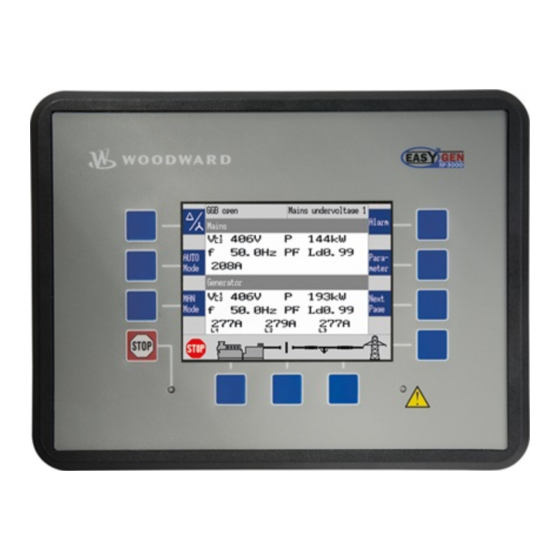
5.2.1 Front Panel
Details the front panel layout, including button groups, LCD display, LEDs, and softkey functions.
5.2.2 Basic Navigation
Explains the basic navigation through the unit's menu screens, including main screen sections and softkey functions.
5.2.3 Standard Menu Screens
Lists standard menu screens such as navigation, status/monitoring, and value setting screens.
5.2.4 Specialised Menu Screens
Details specialized menu screens like main screen voltage display, alarm list, sequencing, and states.
5.3 Change Operating Modes
Explains how to change operating modes, including STOP, MANUAL, and AUTOMATIC modes.
5.4 Restore Language Setting
Provides instructions for restoring the desired language setting, involving softkey operations.
6 Application
6.1 Application Modes
Provides an overview of application modes and special applications, referring to Chapter 6.2 for details.
6.2 Basic Applications
Details basic application modes, including A01 (None), A02 (GCBopen), A03 (GCB), A04 (GCB/MCB), A05 (GCB/GGB), A06 (GCB/GGB/MCB), A07 (GCB/LS5), A08 (GCB/L-MCB), A09 (GCB/GGB/L-MCB), A10 (GCB/L-GGB), A11 (GCB/L-GGB/L-MCB).
6.2.1 Application Mode A01 (None)
Describes application mode A01 where breaker control is external, functioning as engine control with protection.
6.2.2 Application Mode A02 (GCBopen)
Describes application mode A02 for isolated operation, functioning as engine control with generator and engine protection.
6.2.3 Application Mode A03 (GCB)
Describes application mode A03 where only the GCB is operated, for isolated or mains parallel operations.
6.2.4 Application Mode A04 (GCB/MCB)
Describes application mode A04 for mains parallel operation, functioning as engine control with generator, mains, and engine protection.
6.2.5 Application Mode A05 (GCB/GGB)
Describes application mode A05 where a common generator group breaker connects the generator busbar with the load.
6.2.6 Application Mode A06 (GCB/GGB/MCB)
Describes application mode A06 for mains parallel operation, functioning as engine control with generator, mains, and engine protection.
6.2.7 Application Mode A07 (GCB/LS5)
Describes application mode A07 for applications where several breakers operate by LS-5, supporting isolated or parallel to mains operation.
6.2.8 Application Mode A08 (GCB/L-MCB)
Describes application mode A08 for mains parallel operation, functioning as engine control with generator and engine protection.
6.2.9 Application Mode A09 (GCB/GGB/L-MCB)
Describes application mode A09 for mains parallel operation, functioning as engine control with generator and engine protection.
6.2.10 Application Mode A10 (GCB/L-GGB)
Describes application mode A10 for isolated operation, functioning as engine control with generator and engine protection.
6.2.11 Application Mode A11 (GCB/L-GGB/L-MCB)
Describes application mode A11 for mains parallel operation, functioning as engine control with generator and engine protection.
6.3 Multiple Genset Applications
Provides an overview of multiple genset applications, including signals and feedback used.
6.3.1 Configuring Load-Dependent Start/Stop
Details the configuration of load-dependent start/stop for isolated and mains parallel operation.
6.3.2 Configuring Automatic Operation
Explains how to configure automatic operation, including engine start conditions and LogicsManager functions.
6.3.3 Configuring Emergency Operation
Details how to configure emergency operation based on mains failure or MCB failure.
6.4 Special Applications
Covers special applications such as generator excitation protection and analog input configuration.
6.4.1 Generator Excitation Protection
Explains power factor monitoring and protection for generator over- and under-excitation.
6.4.2 Configuring A Setpoint Control Via Analog Input
Illustrates how to configure an easYgen to use an external load setpoint via analog input.
6.4.3 Creating Self-Toggling (Pulsing) Relays
Explains how to create self-toggling relay outputs using LogicsManager.
6.4.4 Changing A Starter Battery Set
Provides programming examples for changing starter battery sets using LogicsManager.
6.4.5 Performing Remote Start/Stop, Shutdown, And Acknowledgement
Details how to configure start/stop/shutdown/acknowledgement functions remotely via CAN/Modbus interface.
6.4.6 Connecting A GSM Modem
Explains how to establish a cellular connection using a GSM modem for mobile use and alarm triggering.
6.4.7 Configuring A PWM Duty Cycle For A CAT ADEM Controller
Details how to configure PWM duty cycle for a CAT ADEM speed controller, limiting duty cycle between 10% and 85%.
6.4.8 Connecting A Landline Modem
Explains how to establish a phone connection using a landline modem for stationary use and alarm triggering.
6.4.9 Connecting A GSM Modem
Explains how to configure the GSM modem for application, including settings for sending alarm messages.
7 Interfaces And Protocols
7.1 Interfaces Overview
Provides an overview of the interfaces supported by the easYgen, including CAN, RS-232, and RS-485.
7.2 CAN Interfaces
Details the CAN interfaces, including CAN Interface 1, 2, and 3, and their supported protocols.
7.2.1 CAN Interface 1 (Guidance level)
Describes the CANopen interface 1, its configuration, and supported objects.
7.2.2 CAN Interface 2 (Engine level)
Details CAN interface 2, supporting CANopen and J1939 protocols for engine control units.
7.2.3 CAN Interface 3 (System level)
Describes CAN interface 3 used for load sharing and LS-5 communication.
7.3 Serial Interfaces
Details serial interfaces, including RS-232 and RS-485 interfaces.
7.3.1 RS-232 Interface (Serial Interface 1)
Describes the RS-232 interface for configuring the unit and visualizing data.
7.3.2 RS-485 Interface (Serial Interface 2)
Describes the RS-485 interface for PLC connectivity and remote control.
7.4 CANopen Protocol
Explains the CANopen protocol, including its communication standard and application layer.
7.5 J1939 Protocol
Details the J1939 protocol, including supported ECUs and displayed messages.
7.5.1 Displayed Messages (Visualization)
Explains how visualization messages are displayed for ECUs based on J1939 protocol.
7.5.2 Supported J1939 ECUs & Remote Control Messages
Lists supported J1939 ECUs and remote control messages, with details on device type and settings.
7.5.3 Device Type Standard
Describes the device type standard for J1939 protocol and ECU compatibility.
7.6 Modbus Protocol
Explains the Modbus protocol, its applications, and how to access data points.
8 Technical Specifications
8.1 Technical Data
Provides comprehensive technical data including measuring values, ambient variables, inputs/outputs, interface specifications, and approvals.
8.1.1 Measuring Values
Details measuring values for voltages, currents, frequency, power, and power factor.
8.1.2 Ambient Variables
Lists ambient variables such as measuring frequency, input resistance, and maximum power consumption.
8.1.3 Inputs/Outputs
Details discrete and analog inputs/outputs, including their potential free configuration and wiring.
8.1.4 Interface
Describes the interfaces supported by the unit: RS-232, RS-485, and CAN bus.
8.1.5 Battery
Provides information on the battery type, life span, and replacement.
8.1.6 Housing
Details housing types (plastic, sheet metal), dimensions, front cutout, wiring, and weight.
8.1.7 Approvals
Lists approvals and certifications applicable to the unit.
8.1.8 Generic Note
Provides general notes regarding the device.
8.2 Environmental Data
Details environmental data including vibration and shock specifications.
8.3 Accuracy
Specifies accuracy for frequency, voltage, current, power, and power factor measurements.
9 Appendix
9.1 Characteristics
Details characteristics of the unit, including triggering characteristics and VDO inputs.
9.1.1 Triggering Characteristics
Describes triggering characteristics for time-dependent over-/undershoot monitoring and phase rotation.
9.1.2 VDO Inputs Characteristics
Provides characteristics for VDO inputs, including pressure and temperature sensors.
9.2 Data Protocols
Details data protocols such as CANopen/Modbus and specific protocols like J1939.
9.2.1 CANopen/Modbus
Covers CANopen/Modbus data protocols, including basic visualization and specific protocols.
9.2.1.1 Data Protocol 5003 (Basic Visualization)
Details the data protocol 5003 for basic visualization in CANopen.
9.2.2 CANopen
Details CANopen protocol, including J1939 standard, supported ECUs, and remote control messages.
9.2.2.1 Protocol 4103 (J1939 Standard Visualization)
Describes J1939 standard visualization protocol for ECUs like Scania and Deutz.
9.2.2.2 Protocol 4104 (J1939 Scania S6 Visualization)
Details J1939 Scania S6 visualization protocol for ECUs.
9.2.2.3 Protocol 4105 (J1939 Deutz EMR2 Visualization)
Describes J1939 Deutz EMR2 visualization protocol for ECUs.
9.2.2.4 Protocol 4110 (J1939 MTU ADEC Visualization)
Details J1939 MTU ADEC visualization protocol for ECUs.
9.2.2.5 Protocol 5004 (Generator Values Visualization)
Describes protocol 5004 for visualizing generator values.
9.2.2.6 Protocol 5005 (Mains Values Visualization)
Details protocol 5005 for visualizing mains values.
9.2.2.7 Protocol 5011 (Alarm Values Visualization)
Describes protocol 5011 for visualizing alarm values.
9.2.2.8 Protocol 6000 (Load Share Message)
Details protocol 6000 for load share messages.
9.2.2.9 Protocol 6003 (LS-5 Communication)
Explains protocol 6003 for LS-5 communication.
9.2.2.10 Protocol 65000 (External Discrete I/O 1 to 8)
Details protocol 65000 for external discrete inputs/outputs 1 to 8.
9.2.2.11 Protocol 65001 (External Discrete I/O 9 to 16)
Describes protocol 65001 for external discrete inputs/outputs 9 to 16.
9.2.2.12 Protocol 65002 (External Discrete I/O 17 to 24)
Details protocol 65002 for external discrete inputs/outputs 17 to 24.
9.2.2.13 Protocol 65003 (External Discrete I/O 25 to 32)
Explains protocol 65003 for external discrete inputs/outputs 25 to 32.
9.2.3 Modbus
Covers the Modbus protocol, including basic visualization and parameter settings.
9.2.3.1 Protocol 5010 (Basic Visualization)
Details protocol 5010 for basic visualization via Modbus.
9.2.4 Additional Data Identifier
Provides additional data identifiers for transmit and receive data.
9.2.4.1 Transmit Data
Explains how to transmit data, including remote control word and examples.
9.3 Analog Manager Reference
Provides reference for the Analog Manager, including data sources and groups.
9.3.1 Data Sources
Details data sources available for analog inputs and outputs.
9.3.1.1 Group 00: Internal Values
Lists internal values for analog inputs, including engine speed, voltage, and current.
9.3.1.2 Group 01: Generator Values
Details generator values such as voltage, frequency, current, and power factor.
9.3.1.3 Group 02: Mains Values
Provides mains values such as voltage, frequency, current, power factor, and reactive power.
9.3.1.4 Group 03: Busbar 1 Values
Details busbar 1 values including voltage, frequency, current, and power factor.
9.3.1.5 Group 05: Controller Setpoints
Lists controller setpoints for frequency, voltage, load, and power factor.
9.3.1.6 Group 06: DC Analog Input Values
Details DC analog input values for various sensors.
9.3.1.9 Group 09: Engine Values 2 (J1939)
Provides engine values for J1939 interface, including temperatures and pressures.
9.3.2 Reference Values
Lists reference values for generator, mains, and busbar parameters.
9.3.2.1 Generator Rated Voltage
Details generator rated voltage and analog output examples.
9.3.2.2 Generator Rated Current
Provides generator rated current values and analog output examples.
9.3.2.3 Rated Frequency
Details rated frequency for generator, mains, and busbar.
9.3.2.4 Generator Rated Active Power
Provides generator rated active power values and analog output examples.
9.3.2.5 Generator Rated Reactive Power
Details generator rated reactive power values and analog output examples.
9.3.2.6 Mains Rated Voltage
Provides mains rated voltage values and analog output examples.
9.3.2.7 Mains Rated Reactive Power
Details mains rated reactive power values and analog output examples.
9.3.2.8 Generator Rated Apparent Power
Provides generator rated apparent power values and calculations.
9.3.2.9 Mains Rated Apparent Power
Details mains rated apparent power values and calculations.
9.3.2.10 Generator / Mains Power Factor
Explains generator and mains power factor scaling.
9.3.2.11 Generator Rated Current
Provides generator rated current values.
9.3.2.12 Mains Rated Current
Details mains rated current values.
9.3.2.13 Rated Speed
Provides information on rated speed.
9.3.2.14 Battery Voltage
Details battery voltage and auxiliary excitation values.
9.3.2.15 Busbar 1 Rated Voltage
Provides busbar 1 rated voltage values.
9.3.2.16 Display Value Format
Explains the display value format for analog inputs and outputs.
9.4 LogicsManager Reference
Provides reference for LogicsManager, including overview, logical symbols, and command variables.
9.4.1 LogicsManager Overview
Explains the LogicsManager overview, including simple functions, extended configuration, and results.
9.4.4 Group 04: Applications Condition
Details applications condition and logic command variables.
9.4.4.5 Group 23: External Discrete Outputs 2
Lists external discrete outputs and their corresponding LogicsManager functions.
9.4.4.6 Group 24: Flags Condition 2
Details flags condition 2 and related LogicsManager variables.
9.4.4.7 Group 25: Flags Of LS5 (33...)
Lists flags of LS5 devices and their corresponding LogicsManager command variables.
9.4.4.8 Group 26: Flags Of LS5 (49...)
Details flags of LS5 devices and their corresponding LogicsManager command variables.
9.4.4.9 Group 27: Flags Of LS5 (49...)
Lists flags of LS5 devices and their corresponding LogicsManager command variables.
9.4.4.10 Group 28: LS5 System Conditions
Details LS5 system conditions and related LogicsManager command variables.
9.4.5 Factory Settings
Provides information on factory settings for LogicsManager functions and configuration.
9.5 Event And Alarm Reference
Covers event and alarm references, including alarm classes and status messages.
9.5.1 Alarm Classes
Details the alarm classes and their corresponding actions.
9.5.2 Conversion Factors
Provides conversion factors for various units.
9.5.3 Status Messages
Lists status messages displayed on the main screen.
9.5.4 Event History
Explains how to access and reset the event history.
9.5.4.1 Event Messages
Lists event messages with their corresponding IDs and meanings.
9.5.4.2 Alarm Messages
Details alarm messages, their meanings, and associated parameters.
Need help?
Do you have a question about the easYgen-3400 P2 and is the answer not in the manual?
Questions and answers