
Related Manuals for Woodward EGB-1P


Summary of Contents for Woodward EGB-1P
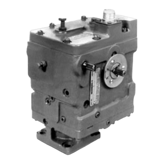
- Page 1 Product Manual 82570 (Revision L, 8/2016) Original Instructions EGB-1P and EGB-2P Governor/Actuator Installation and Operation Manual...
- Page 2 Revisions—Changes in this publication since the last revision are indicated by a black line alongside the text. Woodward reserves the right to update any portion of this publication at any time. Information provided by Woodward is believed to be correct and reliable. However, no responsibility is assumed by Woodward unless otherwise expressly undertaken.
-
Page 3: Table Of Contents
RODUCT UPPORT AND ERVICE PTIONS Product Support Options ..................55 Product Service Options ..................55 Returning Equipment for Repair ................56 Replacement Parts ....................56 Engineering Services .................... 57 Contacting Woodward’s Support Organization ............ 57 Technical Assistance .................... 58 Woodward... - Page 4 EGB-1P/-2P Governor/Actuator Manual 82570 Illustrations and Tables Figure 1-1. EGB-2P Governor/Actuator ..............1 Figure 1-2. EGB-2P and -1P Work Output ............. 2 Figure 1-3. Solenoid Shutdown Connection ............5 Figure 1-4. Outline Drawing of EGB-2P Governor/Actuator ........6 Figure 3-1. Schematic Diagram of EGB-2P Governor/Actuator ......17 Figure 4-1.
- Page 5 Manual 82570 EGB-1P/-2P Governor/Actuator Illustrations and Tables (cont'd.) Figure 5-22. Relief Valve & Piston Sleeve Assembly ........... 40 Figure 5-23. Ballhead Assembly ................41 Figure 5-24. Thrust Bearing & Spring Seat Assembly ......... 41 Figure 5-25. Centering Pilot Valve Plunger ............42 Figure 5-26.
-
Page 6: Warnings And Notices
Start-up On- and off-highway Mobile Applications: Unless Woodward's control functions as the supervisory control, customer should install a system totally independent of the prime mover control system that... -
Page 7: Electrostatic Discharge Awareness
Do not touch the components or conductors on a printed circuit board with your hands or with conductive devices. To prevent damage to electronic components caused by improper handling, read and observe the precautions in Woodward manual 82715 , Guide for Handling and Protection of Electronic Controls, Printed Circuit Boards, and Modules. - Page 8 EGB-1P/-2P Governor/Actuator Manual 82570 Regulatory Compliance North American Compliance: These listings are limited only to those EGB2P Governors bearing the CSA identification. CSA: CSA Certified for Class I, Division 2, Groups A, B, C, & D, T4 at 93 °C ambient. For use in Canada and the United States.
-
Page 9: Chapter 1. General Information
The EGB-1P has the same mounting pad, drive shaft and terminal shaft configuration as the EGB-2P. Internal parts are also identical except for the power piston. The EGB-1P uses a smaller size power piston (see Figures 5-16a and 7-1). -
Page 10: Description
The uses and functions of a proportional actuator are different and distinct from integrating types of EG actuators. The EGB-2P actuator must be used with the Woodward 2301 or 2500 integrating electronic control to form a complete governing system. - Page 11 The proportional actuator requires a continuous electric input signal (in contrast to the nominally zero input signal under steady-state conditions for integrating type actuators). Woodward electronic controls are used to furnish the control input signal for the proportional actuator. The exact control used depends on the operating scheme of the installation.
- Page 12 EGB-1P/-2P Governor/Actuator Manual 82570 A pneumatic start device, using an 80 to 240 psi (550 to 1650 kPa) air signal. (See Auxiliary Devices. Chapter 6.) A manual override device, by pushing and turning a knob mounted on top of the EGB-2P. (See Auxiliary Devices, Chapter 6.) All three methods hold the actuator pilot valve below center to keep the actuator piston in its full up position as needed to obtain mechanical governor control.
-
Page 13: Figure 1-3. Solenoid Shutdown Connection
Manual 82570 EGB-1P/-2P Governor/Actuator Two factors are of primary importance in utilizing external solenoid shutdowns. First is the location of the solenoid. Figure 1-3 following shows the proper connection. Once a suitable connection is decided, the solenoid must be connected with tubing runs as short as possible. The solenoid must also be mounted below the governor and oriented so that it does not fill with air. -
Page 14: Figure 1-4. Outline Drawing Of Egb-2P Governor/Actuator
EGB-1P/-2P Governor/Actuator Manual 82570 Figure 1-4. Outline Drawing of EGB-2P Governor/Actuator Woodward... -
Page 15: Chapter 2. Installation Procedures
If the installation must be changed from vertical to horizontal, or vice versa, a plug must be added or removed, and a new calibration is needed. Return the unit to Woodward for calibration. Linkage Adjustment Maximum and minimum lines on the terminal shaft dial plate (136 on Figure 7-1) indicate the limits of terminal shaft travel during normal operation (approximately 32°). -
Page 16: Electrical Connections
See Figure 1-4, Outline Drawing. Filter is not supplied by Woodward. The engine, turbine, or other type of prime mover should be... - Page 17 Actuator oil must be compatible with seal materials (nitrile, polyacrylic, and fluorocarbon). Many automotive and gas engine oils, industrial lubricating oils, and other oils of mineral or synthetic origin meet these requirements. Woodward actuators are designed to give stable operation with most oils with the viscosity, at the operating temperature, between 50 and 3000 SUS (Saybolt Universal Seconds).
- Page 18 EGB-1P/-2P Governor/Actuator Manual 82570 A loss of stable governor control and possible engine overspeed may result if the viscosity exceeds the 50 to 3000 SUS range. Specific oil viscosity recommendations are given on the Oil Chart (Table 2-1). Select a readily available good brand of oil, either mineral or synthetic, and continue using that same brand.
- Page 19 Manual 82570 EGB-1P/-2P Governor/Actuator Table 2-1. Oil Chart Table 2-2. Viscosity Comparisons Woodward...
-
Page 20: Chapter 3. Principles Of Operation
EGB-1P/-2P Governor/Actuator Manual 82570 Chapter 3. Principles of Operation Introduction This chapter provides information concerning the functional operation of the EGB-2P. The schematic arrangement of the EGB-2P is shown in Figure 3-1 with parts in relative positions assumed during normal operation. Oil enters the unit through either of the two inlet holes in the side of the base. -
Page 21: Actuator Control
Manual 82570 EGB-1P/-2P Governor/Actuator Actuator Control During normal operation the actuator is controlling. At this time the mechanical governor power piston is at the top of its stroke (for reasons to be discussed later). The actuators’ pilot-valve plunger controls the flow of oil to and from its power piston. - Page 22 EGB-1P/-2P Governor/Actuator Manual 82570 With the speed setting of the governor set slightly higher than the actuator, the centrifugal force of the rotating flyweights is not sufficient to lift the pilot-valve plunger to its centered position. Consequently, with the actuator controlling, pressure oil is continually directed to the underside of the governor power piston to hold it up against its stop.
-
Page 23: Speed Droop
Manual 82570 EGB-1P/-2P Governor/Actuator By-pass ports are provided in the buffer cylinder to facilitate large corrective movements of the power piston. A large increase or decrease in the speed setting of the governor, or a large increase or decrease of load on the engine, will require a correspondingly large movement of the power piston to make the necessary correction to the fuel setting. - Page 24 EGB-1P/-2P Governor/Actuator Manual 82570 As a result, the maximum droop that can be obtained depends also on the adjustment of the fuel linkage between the governor and the prime mover, as this adjustment determines how much output shaft travel is used between no load and full load.
-
Page 25: Figure 3-1. Schematic Diagram Of Egb-2P Governor/Actuator
Manual 82570 EGB-1P/-2P Governor/Actuator Figure 3-1. Schematic Diagram of EGB-2P Governor/Actuator Woodward... -
Page 26: Chapter 4. Adjustments
If a test specification sheet is desired for the EGB-2P being tested, contact Woodward at one of the locations listed on the back cover of this manual. Drive the unit in the normal direction of rotation. -
Page 27: Governor Needle Valve Setting
Manual 82570 EGB-1P/-2P Governor/Actuator Figure 4-1. Speed Setting Adapter Plate Make sure to align the pointer with the maximum position on the dial plate by rotating the terminal shaft in the full increase fuel direction. (Both ballhead and electric power pistons in full up position—the mechanical governor underspeeded and the electric actuator pilot valve below center.) -
Page 28: Speed Droop Adjustment
EGB-1P/-2P Governor/Actuator Manual 82570 Speed Droop Adjustment Speed droop is adjustable internally. The speed droop bracket (116 on Figure 7-1) is clamped to the speed droop lever with a set screw. A pin on the droop bracket carries the floating lever (120). When this pin is aligned with the droop lever shaft the droop will be zero. -
Page 29: Figure 4-2. Actuator Test Circuit
Manual 82570 EGB-1P/-2P Governor/Actuator Figure 4-2. Actuator Test Circuit Set test circuit to CENTER. Observe and note direction and position of terminal shaft movement. If terminal shaft moves to another position set test circuit of OFF. (1) For movement towards increase fuel turn pilot valve centering screw (97) slightly clockwise. -
Page 30: Speed Adjustment
EGB-1P/-2P Governor/Actuator Manual 82570 13. Adjust potentiometer for 160 mA or to Max. value signal (see Specification sheet for EGB-2P). Terminal shaft movement should be an additional 29° (±0.5°) towards maximum. 14. If adjustment is necessary, loosen screws (105) slightly and turn eccentric pin (95) in restoring lever (93) as required to shift position of ratio adjustment clamping plate (102). -
Page 31: Adjustments After Tests
Manual 82570 EGB-1P/-2P Governor/Actuator Setting Maximum Speed Adjust the unit’s speed using the speed adjustment screw, speed adjusting shaft or speed setting motor until the desired rated speed is obtained. If droop is used, simulate an underspeed condition until the terminal shaft travels to a position just short (1°... -
Page 32: Chapter 5. Maintenance
EGB-1P/-2P Governor/Actuator Manual 82570 Chapter 5. Maintenance Introduction This chapter includes information for troubleshooting, disassembly, parts check, assembly, and lubrication. In addition to the basic tools, the speed setting adapter plate (Figure 4-1), the actuator test circuit (Figure 4-2), and the pilot valve wrench (Figure 5-1) will be necessary to disassemble, repair, and assemble the unit. -
Page 33: Removing The Egb-2P
Manual 82570 EGB-1P/-2P Governor/Actuator If neither load nor prime mover irregularities are found to be the cause of the speed variation, the cause may be either in the unit or in the drive from the prime mover. The source of most troubles in any hydraulic actuator or governor stems from dirty oil. -
Page 34: Disassembly
EGB-1P/-2P Governor/Actuator Manual 82570 Disassembly Do not disassemble the unit or its various sub-assemblies any further than necessary. Remove screws (153), cover (151) and gasket (150). Remove pins (124) from speeder spring assembly, pin (121) from floating lever (120) and take out floating lever. - Page 35 Manual 82570 EGB-1P/-2P Governor/Actuator 11. Remove screw (110) and retaining ring (108) from terminal shaft (107) and pull shaft from case. Remove bushings (106) only if replacement is necessary, oil seal (134) and felt washer (135) from both sides of the case.
-
Page 36: Figure 5-2. Ballhead Disassembly
EGB-1P/-2P Governor/Actuator Manual 82570 30. Remove oil seal (61), packing (62), plug (56), and packing (55). 31. Remove relief valve parts (51) through (54). 32. Remove rotating bushing (41), pilot valve plunger (42) compensation bushing (43) and retaining ring (44) from case. -
Page 37: Parts Check
Manual 82570 EGB-1P/-2P Governor/Actuator 44. Use an arbor press and Woodward tool 8995-054 to disassemble the ballhead. See Figure 5-2. Press the drive cup and ballhead out of the cover. Disassemble the drive cup, ballhead, bearing and flyweights. Note which side of the bearing is “up”... -
Page 38: Figure 5-4. Speeder Spring Parts Layout
EGB-1P/-2P Governor/Actuator Manual 82570 Speeder spring assembly is shown in Figures 5-4 and 5-5 for reference only. See step (32) for speeder spring assembly. Figure 5-4. Speeder Spring Parts Layout Figure 5-5. Speeder Spring Subassembly Assemble mechanical governor pilot valve bushing, pilot valve plunger, compensating bushing, and retaining ring, Figure 5-6. -
Page 39: Figure 5-7. Actuator Pilot Valve Assembly
Manual 82570 EGB-1P/-2P Governor/Actuator Assemble actuator pilot valve bushing, pilot valve plunger, compensating bushing, magnet adjusting spring and retaining ring. Figure 5-7. Actuator Pilot Valve Assembly Assemble clamp bracket (84), restoring spring assembly (85 to 89), transducer lever (91), restoring lever (93), eccentric pin (95), adjustable spring seat (90), and pilot valve plunger nut (92) per Figure 5-8 Parts Layout and Figure 5-9 Subassembly. -
Page 40: Figure 5-10. Ballhead Parts Layout
Assemble flyweights and pins in ballhead. Use an arbor press and Woodward tool 8995-005 and press the cover in place on the ballhead as shown in Figure 5-11. The cover lip should be flush with the edge of the ballhead. -
Page 41: Figure 5-12. Ballhead Assembly
Manual 82570 EGB-1P/-2P Governor/Actuator Figure 5-12. Ballhead Assembly 10. See Figure 5-13. Assemble packing (14), buffer cap (15), and retaining ring (16) in the case. Assemble packing (10) and screw plug (11) in case. Assemble spring (5), buffer piston (6), spring (5), packing (7), buffer plug (8), and retaining ring (9) in case. -
Page 42: Figure 5-14. Needle Valve Assembly
EGB-1P/-2P Governor/Actuator Manual 82570 11. Assemble needle valve in case (Figure 5-14). Figure 5-14. Needle Valve Assembly 12. See Figure 5-15. Assemble power piston (19) and floating lever (21) with pin (20) and snap ring (22). Assemble pivot link (23) and terminal lever link with pin (27), and fasten together with roll pin (28). -
Page 43: Figure 5-16. Power Piston Assembly (Large Size Piston)
(19A) which is installed from the inside of the actuator case. The small size power piston is used on the EGB-1P only. If the small size piston is to be installed, be sure to slip the collar and the snap ring onto the end of the small piston, after it has been installed in the case. -
Page 44: Figure 5-17. Power Piston Linkage Assembly
EGB-1P/-2P Governor/Actuator Manual 82570 Figure 5-17. Power Piston Linkage Assembly 16. Refer to Figures 5-18 and 5-19. Insert pin (35) into power piston (34). Place this assembly in case. Attach solid end of piston link (36) to power piston (34) with headed pin (37), and secure with a cotter pin. -
Page 45: Figure 5-17B. Raising Power Pistons
Manual 82570 EGB-1P/-2P Governor/Actuator (2) Apply pressure on elastic nut (33) with index finger and raise both pistons (19) & (34) with inside hand. See Figure 5-17b. Remove inside hand quickly to allow piston linkage assembly to drop sharply in order to remove all stickiness and insure proper seating. -
Page 46: Figure 5-17D. Removing Play In Power Piston Assembly
EGB-1P/-2P Governor/Actuator Manual 82570 (3) Fit speed handle to elastic nut (33) and holding speed handle with firm pressure, start turning elastic nut (33) counterclockwise 1/4 of a turn or so at a time to remove play in the piston linkage assembly. Remove... -
Page 47: Figure 5-18. Piston Placement
Manual 82570 EGB-1P/-2P Governor/Actuator Figure 5-18. Piston Placement Figure 5-19. Piston Link Assembly 17. Refer to Figure 5-20 and place packing (62) in base. Lubricate and put packing (55) on plug (56) and push into base. Put bowed spring washer (57) (concave side up) in place on top of plug (56) in base. -
Page 48: Figure 5-21. Bushing Assemblies
EGB-1P/-2P Governor/Actuator Manual 82570 18. Refer to Figure 5-21. Figure 5-21. Bushing Assemblies If idler gear stud (39) has been removed, although this should not be necessary, press it into case until its end is lust below face surface. Insert pilot valve bushing assemblies (41) and (45) and idler gear (60) into case as shown. -
Page 49: Figure 5-23. Ballhead Assembly
Manual 82570 EGB-1P/-2P Governor/Actuator Figure 5-23. Ballhead Assembly 21. Install thrust bearing (68) (race1 bearing, race), speeder spring seat (69) on pilot valve plunger (42) and secure with nut (70). Do not tighten nut (70). 22. Check centering of pilot valve plunger by holding the pilot valve bushing with one hand and pushing on the flyweight toes with the other to lower the pilot valve plunger (PVP) as far as possible. -
Page 50: Figure 5-25. Centering Pilot Valve Plunger
EGB-1P/-2P Governor/Actuator Manual 82570 Figure 5-25. Centering Pilot Valve Plunger 23. Refer to Figure 5-22. Insert sleeve (54), plunger (53), spring (51), and spacer (52) into case. Lubricate base oil seal (61) and place it in groove on base. Assemble base to case and secure it with lock washers (72) and screws (73). -
Page 51: Figure 5-27. Transducer Parts Assembly
Manual 82570 EGB-1P/-2P Governor/Actuator Figure 5-27. Transducer Parts Assembly Figure 5-28. EGB-2P Diagram 25. Install transducer assembly on pilot valve plunger (46) and attach plug (132) to case with screws (133). Be sure connections of plug (132) match the connections in cover. -
Page 52: Figure 5-29. Plug & Transducer Installation
EGB-1P/-2P Governor/Actuator Manual 82570 Figure 5-29. Plug & Transducer Installation Figure 5-30. Clamp Bracket Assembly Figure 5-31. Transducer Compression Spring & Ratio Adjustment Plate Woodward... -
Page 53: Figure 5-32. Terminal Shaft Installation
Manual 82570 EGB-1P/-2P Governor/Actuator 28. Insert terminal shaft (107) through side of case (Figure 5-32) and through terminal lever (29). Secure with retaining ring (108). When inserting shaft, tapered hole in shaft must align with hole in terminal lever. Insert tapered pin (111) into hole tight enough for alignment and thread screw (110) with washer (109) into terminal lever and tighten. -
Page 54: Figure 5-34. Speed Droop Lever Assembly
EGB-1P/-2P Governor/Actuator Manual 82570 Figure 5-34. Speed Droop Lever Assembly 31. Attach dial plates (136 and 140) with screws (137). See Figure 5-35. Place oil seal (134, cup towards case) on terminal shaft using seal installing tools T94157. Turn terminal shaft to maximum position. Place pointers (138) on terminal shaft with pointer pointing at max., and secure them in place with... -
Page 55: Figure 5-36. Speed Adjusting Shaft Assembly
Manual 82570 EGB-1P/-2P Governor/Actuator 33. Insert speed adjusting shaft (126) through case, through speed adjusting lever (123), spacer (127) and into hole on opposite side of case. Figure 5-36 shows an actuator equipped with a stub shaft. Stub shafts require tapered plugs as shown on each side of case. -
Page 56: Manual Override Assembly (Optional)
EGB-1P/-2P Governor/Actuator Manual 82570 Figure 5-39. Final Assembly 34. Install cover (151) and gasket (150) on case with bolts and washers (152 and 153). Manual Override Assembly (optional) Assemble the manual override in the order shown in Figure 5-40. To hold the assembly together compress the assembly and insert pin (159) through knob (158) and through the top of shaft (165). -
Page 57: Lubrication
Manual 82570 EGB-1P/-2P Governor/Actuator Thread the sleeve (161) of the completed assembly down until the terminal shaft is at maximum position. Tighten jam nut (162) against the cover to lock the assembly in place. Unlatch the manual override. The terminal shaft should move back to minimum position. -
Page 58: Chapter 6. Auxiliary Devices
EGB-1P/-2P Governor/Actuator Manual 82570 Chapter 6. Auxiliary Devices Introduction The following is a brief description of the auxiliary devices available for the EGB-2P Governor/Actuator. Manual and Pneumatic Overrides for Actuator The manual and pneumatic overrides provide a means of moving the actuators pilot valve to the full fuel position on the direct acting EGB-2P actuator when control voltage is not available or has failed. -
Page 59: Figure 6-1. Manual Override Assembly
Manual 82570 EGB-1P/-2P Governor/Actuator Figure 6-1. Manual Override Assembly Figure 6-2. Cover with Manual Override Woodward... -
Page 60: Chapter 7. Replacement Parts
The parts breakdown (Figure 7-1) illustrates and lists all the replaceable parts for the EGB-2P Actuator. The numbers assigned are used as reference numbers and are not specific Woodward part numbers. Woodward will determine the exact part number for your particular actuator. - Page 61 Manual 82570 EGB-1P/-2P Governor/Actuator Ref. No. Part Name ......... Quantity Ref. No. Part Name ......... Quantity 82570-76 Washer .281 O.D........1 82570-126 Speed adjusting shaft ......1 82570-77 Straight pin ..........1 82570-127 Spacer ............ 1 82570-78 Piston link ..........1 82570-128 Roll pin, .135 O.D.
-
Page 62: Figure 7-1. Egb-2P Exploded View
EGB-1P/-2P Governor/Actuator Manual 82570 Figure 7-1. EGB-2P Exploded View Woodward... -
Page 63: Chapter 8. Product Support And Service Options
A current list of Woodward Business Partners is available at www.woodward.com/directory. Product Service Options Depending on the type of product, the following options for servicing Woodward products may be available through your local Full-Service Distributor or the OEM or Packager of the equipment system. -
Page 64: Returning Equipment For Repair
To prevent damage to electronic components caused by improper handling, read and observe the precautions in Woodward manual 82715, Guide for Handling and Protection of Electronic Controls, Printed Circuit Boards, and Modules. -
Page 65: Engineering Services
Field Service engineering on-site support is available, depending on the product and location, from one of our Full-Service Distributors. The field engineers are experienced both on Woodward products as well as on much of the non- Woodward equipment with which our products interface. -
Page 66: Technical Assistance
Manual 82570 Technical Assistance If you need to contact technical assistance, you will need to provide the following information. Please write it down here before contacting the Engine OEM, the Packager, a Woodward Business Partner, or the Woodward factory: General... - Page 68 Email and Website—www.woodward.com Woodward has company-owned plants, subsidiaries, and branches, as well as authorized distributors and other authorized service and sales facilities throughout the world. Complete address / phone / fax / email information for all locations is available on our website.
Need help?
Do you have a question about the EGB-1P and is the answer not in the manual?
Questions and answers