
Related Manuals for Woodward EG-6P


Summary of Contents for Woodward EG-6P
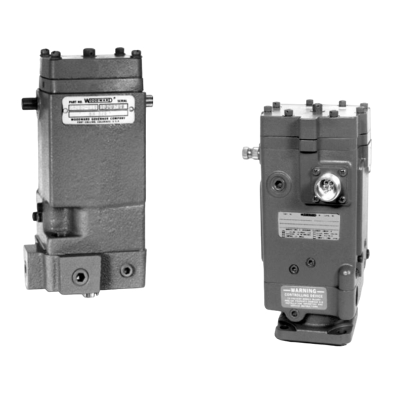
- Page 1 Released Product Manual 82566 (Revision U, 1/2019) Original Instructions EG-6P, EG-6PC, EG-10P, EG-10PC Actuators Proportional and Proportional with Compensation Oil Pump and Oil Motor Models Installation and Operation Manual...
- Page 2 Revisions—Changes in this publication since the last revision are indicated by a black line alongside the text. Woodward reserves the right to update any portion of this publication at any time. Information provided by Woodward is believed to be correct and reliable. However, no responsibility is assumed by Woodward unless otherwise expressly undertaken.
-
Page 3: Table Of Contents
References ......................8 Specifications ......................8 2. I ..............11 HAPTER NSTALLATION Storage ......................... 11 Installation......................11 EG-6P, EG-10P Actuator (with Compensation) ........... 12 Oil Supply ......................13 3. P ........... 20 HAPTER RINCIPLES OF PERATION Introduction ......................20 Oil Pump Model ....................20 Oil Motor Model .................... - Page 4 Figure 5-2. Parts for the EG-P Actuator (Oil Pump Model) ........31 Table 1-1. Governor Oil Pressure vs Maximum Work Output ........ 7 Table 2-1. Orifice Size for Oil Motor Supply Pressure..........14 The following are trademarks of Woodward, Inc.: EG-6P, EG-6PC, EG-10P, EG-10PC The following are trademarks of their respective companies:...
-
Page 5: Warnings And Notices
Start-up On- and off-highway Mobile Applications: Unless Woodward's control functions as the supervisory control, customer should install a system totally independent of the prime mover control system that... -
Page 6: Electrostatic Discharge Awareness
Do not touch the components or conductors on a printed circuit board with your hands or with conductive devices. To prevent damage to electronic components caused by improper handling, read and observe the precautions in Woodward manual 82715 , Guide for Handling and Protection of Electronic Controls, Printed Circuit Boards, and Modules. -
Page 7: Regulatory Compliance
These hazardous locations listings are limited to those units bearing the UL, CSA, or LCIE agency identification, specific hazardous locations markings, and the CE marking. If the unit will be used in hazardous locations, refer to the product nameplate or contact your Woodward account manager for more information. Woodward... - Page 8 Released EG-6P/PC, EG-10P/PC Actuator Manual 82566 The EG-10P actuator is suitable for use in Class I, Division 1, Groups B, C, and D per UL for the US or non-hazardous locations only. The EG-10P actuator is suitable for use in Class I, Division 2, Groups B, C, and D per UL for the US or non-hazardous locations only.
-
Page 9: Chapter 1. General Information
Released Manual 82566 EG-6P/PC, EG-10P/PC Actuator Chapter 1. General Information Description The controlling element of the EG-6 and EG-10 Proportional Actuators is an electrohydraulic transducer which controls oil flow to and from the power piston through the action of a polarized solenoid. The position of the actuator output shaft is proportional to the input current of the solenoid coil controlling the hydraulic pilot-valve plunger. -
Page 10: References
All Models 0.375”-36 serrations (standard/EG-3P) both sides of Output Shaft the case; 0.500”-36 serrations (standard/ EG-6P/10P) either side of the case. Special output shafts are available. Angular Travel 42° nominal travel available with 28° travel from no load to full load at rated speed recommended Calibration 2°... - Page 11 Electrical Connector 4-pin MS-33682-14S-2P. UL design does not have connector Hydraulic Oil Supply Fluid Hydrocarbon oil. Consult Woodward for recommended synthetic oils. If multi-viscosity oils are used, the compensated model is suggested. Hydraulic Oil Viscosity 100 to 200 SUS at operating temperature recommended.
- Page 12 Released EG-6P/PC, EG-10P/PC Actuator Manual 82566 Oil Motor (EG-10P) Work Output: Recommended Output Shaft Actuator Operating Maximum Work Travel is 2/3 full travel Oil Pressure Output for a work output of: 400 psi 2758 kPa 9.3 Nm 12.6 ft-lb 6.2 Nm 8.4 ft-lb...
-
Page 13: Chapter 2. Installation
Released Manual 82566 EG-6P/PC, EG-10P/PC Actuator Chapter 2. Installation This chapter provides information for the receiving, storage, and installation of the EG-10P actuator. See Figures 2-2, and 2-3 for typical outline drawings. Storage For short-term storage, fill the actuator with a good rust and oxidation inhibited oil. -
Page 14: Eg-6P, Eg-10P Actuator (With Compensation)
C and D in the mating plug. RVDT or minimum-position switch features will require different electrical connections. Actuators designed for use in hazardous environments have conduit boxes permanently attached. EG-6P, EG-10P Actuator (with Compensation) Description Many EG actuators operate with oil supplied directly from the prime mover. -
Page 15: Oil Supply
Released Manual 82566 EG-6P/PC, EG-10P/PC Actuator Oil Supply Clean Supply Dirt in the oil can cause the actuator to malfunction. Many oil pump model actuators are installed with a direct line from either the engine pressure oil system or from the engine oil sump. A 20 to 25 µm absolute filter should be installed in the line from the engine. -
Page 16: Figure 2-1. Oil Viscosity Chart
Released EG-6P/PC, EG-10P/PC Actuator Manual 82566 Adequate drain is important for dependable and stable operation of the oil motor actuator. A minimum of 25 mm (1 inch) ID drain is needed with a continuous drop for up to 3 m (10 ft) from the actuator. Drains longer than 3 m (10 ft) will probably require larger ID pipe. -
Page 17: Figure 2-2. Outline Drawing Of Typical Eg-P Actuator (Oil Pump Model)
Released Manual 82566 EG-6P/PC, EG-10P/PC Actuator Figure 2-2. Outline Drawing of Typical EG-P Actuator (Oil Pump Model) Woodward... -
Page 18: Figure 2-3. Outline Drawing Of Typical Eg-P Actuator (Oil Motor Model)
Released EG-6P/PC, EG-10P/PC Actuator Manual 82566 Figure 2-3. Outline Drawing of Typical EG-P Actuator (Oil Motor Model) Woodward... -
Page 19: Figure 2-4. Outlines Of Typical Applications
Released Manual 82566 EG-6P/PC, EG-10P/PC Actuator Figure 2-4. Outlines of Typical Applications (Pickering RVDT options, minimum-position switch options, and UL wiring options for installation in hazardous locations) Woodward... -
Page 20: Figure 2-5. Oil Pump Rotation Plugs
Released EG-6P/PC, EG-10P/PC Actuator Manual 82566 Figure 2-5. Oil Pump Rotation Plugs Woodward... -
Page 21: Figure 2-6. Eg-10P Oil Pump Actuator
Released Manual 82566 EG-6P/PC, EG-10P/PC Actuator Figure 2-6. EG-10P Oil Pump Actuator Woodward... -
Page 22: Chapter 3. Principles Of Operation
Released EG-6P/PC, EG-10P/PC Actuator Manual 82566 Chapter 3. Principles of Operation Introduction The EG actuator consists of the following basic items: Oil pump or oil motor Relief valve (oil pump model only) Pilot valve plunger and rotating bushing Magnet (transducer assembly) -
Page 23: Oil Motor Model
Released Manual 82566 EG-6P/PC, EG-10P/PC Actuator Figure 3-1. EG-P Schematic With the unit running on-speed under steady-state conditions, the resulting spring force and the force from the current in the solenoid coils are equal but opposite. This keeps the output shaft at a position to maintain the engine at the required speed. -
Page 24: Voltage Change
Released EG-6P/PC, EG-10P/PC Actuator Manual 82566 The oil motor portion of the actuator operates with a restriction to the pressure oil supply in order to reduce the flow of pressure oil through the oil motor. The orifice is normally fitted internally in the actuator. Some actuators are built without an internal orifice and, in these cases, a separate oil supply and orifice is required. -
Page 25: Figure 3-2. Eg-P Compensation System
Released Manual 82566 EG-6P/PC, EG-10P/PC Actuator Figure 3-2. EG-P Compensation System Woodward... -
Page 26: Chapter 4. Troubleshooting
Released EG-6P/PC, EG-10P/PC Actuator Manual 82566 Chapter 4. Troubleshooting This chapter gives instructions for checking the operation of the EG actuator. See the appropriate manual for troubleshooting your electronic governor system. The problems encountered with a new or factory rebuilt actuator are usually limited to installation and supply oil problems. -
Page 27: Figure 4-1. Wiring Diagram For Circuit To Test Actuator Output
Released Manual 82566 EG-6P/PC, EG-10P/PC Actuator Figure 4-1. Wiring Diagram for Circuit to Test Actuator Output Do not circumvent safety features of the actuator when servicing or troubleshooting an actuator designed for use in hazardous locations. Woodward... -
Page 28: Chapter 5. Replacement Parts
Manual 82566 Chapter 5. Replacement Parts This chapter provides information for replacement parts for the EG-6P and EG-10P actuators. Figure 5-1 shows parts for the EG actuator with an oil motor. Figure 5-2 shows the EG actuator with an oil pump. - Page 29 Released Manual 82566 EG-6P/PC, EG-10P/PC Actuator Ref. No. Part Name Quantity 82566-37 Magnet ..............1 82566-38 Coil cover ..............1 82566-39 Centering spring assembly ........1 82566-40 Washer ..............1 82566-41 Centering screw 6-32 x .375 ........1 82566-42 Connector gasket ............1 82566-43 4 pin receptacle ............
-
Page 30: Figure 5-1. Parts For The Eg Actuator (Oil Motor Model)
Manual 82566 Parts for UL connections, Pickering or Kearfott RVDT options, and minimum position switch options, are not listed. Contact Woodward for information about these options. The serial number and part number shown on the nameplate of the individual control will determine the designs of these special features. -
Page 31: Parts For Figure 5-2
Released Manual 82566 EG-6P/PC, EG-10P/PC Actuator Parts for Figure 5-2 Ref. No. Part Name Quantity 82566-101 EG-10P case and standpipe ........1 82566-102 Pipe plug .250 NPTF ..........2 82566-103 Soc. hd. plug .0625 NPTF ......... 6 82566-104 Shipping plug .250 NPTF .......... 2 82566-105 Nameplate .............. - Page 32 Released EG-6P/PC, EG-10P/PC Actuator Manual 82566 Ref. No. Part Name Quantity 82566-157 Socket head cap screw, Io x 2.250” ......2 82566-158 Loading lever ............1 82566-159 Soc. cap screw 10-32 x .625 ........1 82566-160 Drilled pin .250 x .656 ..........1 82566-161 Pin ................
-
Page 33: Figure 5-2. Parts For The Eg-P Actuator (Oil Pump Model)
EG-6P/PC, EG-10P/PC Actuator * NOTE–Used with EG-10P only Parts for UL connections, Pickering or Kearfott RVDT options, and minimum-position switch options, are not listed. Contact Woodward for information about these options. Figure 5-2. Parts for the EG-P Actuator (Oil Pump Model) -
Page 34: Chapter 6. Product Support And Service Options
A current list of Woodward Business Partners is available at www.woodward.com/directory. Product Service Options Depending on the type of product, the following options for servicing Woodward products may be available through your local Full-Service Distributor or the OEM or Packager of the equipment system. -
Page 35: Returning Equipment For Repair
To prevent damage to electronic components caused by improper handling, read and observe the precautions in Woodward manual 82715, Guide for Handling and Protection of Electronic Controls, Printed Circuit Boards, and Modules. -
Page 36: Engineering Services
Field Service engineering on-site support is available, depending on the product and location, from one of our Full-Service Distributors. The field engineers are experienced both on Woodward products as well as on much of the non- Woodward equipment with which our products interface. -
Page 37: Technical Assistance
EG-6P/PC, EG-10P/PC Actuator Technical Assistance If you need to contact technical assistance, you will need to provide the following information. Please write it down here before contacting the Engine OEM, the Packager, a Woodward Business Partner, or the Woodward factory: General... -
Page 38: Revision History
Released EG-6P/PC, EG-10P/PC Actuator Manual 82566 Revision History Changes in Revision U— Revised hydraulic oil viscosity specification Changes in Revision T— Updated regulatory compliance section Updated Declaration of Conformity and Declaration of Incorporation Changes in Revision R—... -
Page 39: Declarations
Released Manual 82566 EG-6P/PC, EG-10P/PC Actuator Declarations Woodward... - Page 40 Released EG-6P/PC, EG-10P/PC Actuator Manual 82566 Woodward...
- Page 41 Released Manual 82566 EG-6P/PC, EG-10P/PC Actuator THIS PAGE INTENTIONALLY LEFT BLANK Woodward...
- Page 42 82566U Please reference publication ËB82566è:U´ ¹ µ ¹ ¶ ¸ Î PO Box 1519, Fort Collins CO 80522-1519, USA 1041 Woodward Way, Fort Collins CO 80524, USA Phone +1 (970) 482-5811 Email and Website—www.woodward.com Woodward has company-owned plants, subsidiaries, and branches, as well as authorized distributors and other authorized service and sales facilities throughout the world.
Need help?
Do you have a question about the EG-6P and is the answer not in the manual?
Questions and answers