
Related Manuals for JUMO Quantrol LC300


Summarization of Contents
1 Introduction
1.1 Device Documentation
Overview of available documentation for the device, including data sheets and manuals.
1.2 Safety Information
Crucial safety instructions, warnings, and precautions for operating the device safely.
2 Installation - Electrical Connection
2.1 Identifying Device Version
Guide to identifying the device model and its specific configuration options.
2.2 Technical Data Excerpt
Key technical specifications including dimensions, panel cut-out, and environmental conditions.
Electrical Data
Detailed electrical specifications such as voltage supply, power consumption, and connection requirements.
2.3 Installation Procedure
Step-by-step instructions for physically installing the controller into a panel.
2.4 Installation Notes
Important guidelines and precautions for safe and compliant installation of the device.
2.5 Electrical Isolation
Diagram illustrating electrical isolation principles for various device interfaces.
2.6 Connection Diagram
Visual guide showing terminal connections for different device models (LC100, LC200, LC300).
Connection Terminal Assignments
Table detailing terminal assignments for analog inputs, outputs, binary inputs, and interfaces.
3 Operation - Configuration - Parameterization
3.1 Operation Overview
Introduction to device operation, display elements, and basic control functions.
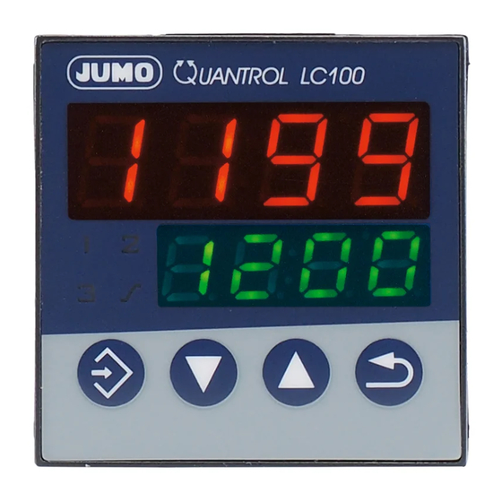
3.1.1 Display and Operating Elements
Detailed explanation of the device's displays, LEDs, and buttons.
3.1.4 Level Concept
Explanation of the hierarchical parameter structure and navigation principles.
3.1.5 Operator Level (OPr)
Parameters accessible to the operator, such as setpoints and timer values.
3.2 Configuration (ConF)
Introduction to the configuration level for setting up device functions and inputs/outputs.
3.2.1 Analog Input (InP)
Configuration options for analog inputs, including sensor types and signal ranges.
3.2.2 Controller (Cntr)
Configuration settings for controller type, action, and output behavior.
3.2.3 Ramp Function/Firing Curve (rAFC)
Configuration of ramp functions and firing curves for controlled heating or cooling profiles.
3.2.4 Limit Value Monitoring (Li1, Li2)
Setting up limit value monitoring and alarm functions for process safety.
3.2.5 Timer (tFCt)
Configuration of timer functions for time-limited control or setpoint changeovers.
3.2.6 Outputs (OutL, OutA)
Configuration of binary and analog outputs, defining their functions and signal types.
3.2.7 Binary Functions (binF)
Configuration of binary inputs and timer signals to trigger various device operations.
3.2.8 Display and Operation (diSP)
Customization of device displays and function key behavior.
3.2.9 Interface (IntF)
Configuration of communication interfaces like RS485 for data network integration.
3.3 Parameterization (PArA)
Detailed controller parameter settings for tuning control loops (PID, PI).
4 Supplement
1.3 Scope of Delivery
Lists the items included in the package, such as the controller and brief instructions.
4.1 Additional Installation Information
Supplementary information and notes related to the device installation.
4.1.1 Device Dimensions (LC100)
Technical drawings and dimensions for the LC100 model, including panel cut-out.
4.1.1 Device Dimensions (LC200)
Technical drawings and dimensions for the LC200 model, including panel cut-out.
4.1.1 Device Dimensions (LC300)
Technical drawings and dimensions for the LC300 model, including panel cut-out.
4.1.2 Cleaning the Device Front
Guidelines for cleaning the device's front panel using appropriate agents.
4.2 Additional Device Functions
Further details on device functions and advanced operational aspects.
4.2.1 Entries and Operator Prompting
Explains the process of entering values and responding to prompts on the device.
4.2.2 Analog Input & Output Details
In-depth information on measured value offset, filter time constants, and output settings.
4.2.4 Ramp Function and Firing Curve
Comprehensive explanation of ramp function and firing curve operation.
4.2.5 Timers
Details on realizing time-limited control and time-dependent setpoint changes using timers.
4.2.6 Limit Value Monitoring
Graphical representation of limit value monitoring and alarm functions.
4.2.7 Self-Optimization (TUNE)
Explanation of self-optimization for PID/PI controllers and its parameters.
Self-Optimization Prerequisites
Conditions that must be met before starting self-optimization and controller configurations.
Start and Abort Self-Optimization
Instructions for initiating and stopping the self-optimization process.
4.3 Error Messages
List of error messages, their causes, and remedies for troubleshooting.
4.4 Technical Data
Comprehensive technical specifications for various inputs, outputs, and general device data.
Standard Signal, Binary Input, and Output Specs
Technical data for standard signal inputs, binary inputs, and output characteristics.
Controller, Electrical, and Case Specs
Summary of controller types, electrical data, and case dimensions and requirements.
Interface, Display, and Approvals
Information on interfaces, display characteristics, and device approval marks.
Need help?
Do you have a question about the Quantrol LC300 and is the answer not in the manual?
Questions and answers