Table of Contents
Advertisement
Quick Links
98585A
High Intensity LED Stroboscope Digital Tachometer
DT-361/365
Instruction manual
Be sure to read before use.
Before use, please carefully read these safety precautions as well as instructions,
and follow them for proper use.
GlobalTestSupply
www.
.com
nd Quality Products Online at:
sales@GlobalTestSupply.co
Advertisement
Table of Contents

Related Manuals for Shimpo DT-365


Summary of Contents for Shimpo DT-365
- Page 1 98585A High Intensity LED Stroboscope Digital Tachometer DT-361/365 Instruction manual Be sure to read before use. Before use, please carefully read these safety precautions as well as instructions, and follow them for proper use. GlobalTestSupply www. .com nd Quality Products Online at:...
- Page 2 Safety Requirements Be sure to observe Before operation, maintenance and inspection, please carefully read this instruction manual and follow it for proper use. Please carefully read all information related to this unit's safety precautions before use. This instruction manual provides two grades of safety warnings: Danger and Caution. Each of them is an important description related to safety.
-
Page 3: Table Of Contents
- Contents - Overview Before use Checking accessories Peel off the protection sheet Charging (only for DT-365) 2.3.1 Charging method 2.3.2 Indication of low battery voltage 2.3.3 Battery replacement Part names and functions Main unit Operation section Display 3.3.1 Part names 3.3.2 Number display 3.3.3... -
Page 4: Overview
Refer to 4.4 External synchronous emission for details Before use Checking accessories Check that the three items in the table below are supplied. DT-361 DT-365 DT-361 x 1 DT-365 x 1 Main unit External signal I/O connector (8 pin) x 1 Dedicated AC adapter x 1 RM15WTP-8S(7) -
Page 5: Peel Off The Protection Sheet
Peel off the protection sheet Peel off the protection sheet on the operation section. Operation section Peel off the (transparent) protection sheet Charging (only for DT-365) Be sure to charge the battery before initial use. Before charging, be sure to check that the power is turned OFF. -
Page 6: Indication Of Low Battery Voltage
2.3.2 Indication of low battery voltage If the remaining battery power drops to near zero, the number display alternates between the process setting and LLLLLL. However, operation can be performed even when the battery is in this low condition. If the remaining battery decreases further, the number display indicates only LLLLLL, which then stops operation. -
Page 7: Part Names And Functions
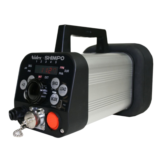
Part names and functions Main unit Super luminosity LED (18 lights) Operation section External I/O connector Power switch * The image is for DT-365. Operation section ⑤ ⑥ ④ ⑦ ③ ② ⑧ ① * The image is for DT-365. Name Function description Power switch... -
Page 8: Display
Display 3.3.1 Part names Charging lamp (only for DT-365) Memory number display Numerical display Mode display Unit display Emission setting display 3.3.2 Number display •Indicates the setting value of the emission count (frequency) in internal oscillation emission mode. •Indicates the external signal frequency in external synchronous emission mode. •Each setting value is indicated in the function setting mode. -
Page 9: Functions And Operations
Functions and operations Power ON/OFF Press the power switch when the power is OFF to turn the power ON. When the power is turned ON, the model is indicated, followed by internal oscillation emission or external synchronous emission. Operation Display When the power is Internal oscillation emission when the power was last OFF... -
Page 10: Emission Setting
Emission setting Each press of the SIG key switches between internal oscillation emission and external synchronous emission. Operation Display Internal oscillation emission External synchronous emission Each press switches the emission settings GlobalTestSupply www. .com nd Quality Products Online at: sales@GlobalTestSupply.co... -
Page 11: Internal Oscillation Emission
Internal oscillation emission 4.3.1 Display of internal oscillation emission Setting value Mode display Memory number display Display showing internal oscillation emission 4.3.2 Switching the modes Each press of MODE key switches the setting display value to FPM (emission count mode), DUR (emission duration mode), and PHA (phase mode). -
Page 12: Emission Count Mode
4.3.4 Emission count mode The emission count (frequency) can be set in the emission count mode (FPM). 4.3.4.1 Emission count setting Turn the dial to the CW direction to increase the emission count (frequency), and to the CCW direction to decrease it. Turn the dial fast to change the setting value greatly and slowly to change it slightly. -
Page 13: Changing The Emission Count (Frequency) To Double Or Half
4.3.4.2 Changing the emission count (frequency) to double or half The emission count (frequency) can be changed to double or half of the current setting value using the key operation on internal oscillation emission. 1) To change the emission count (frequency) to double of the current setting value Each press of the x2 key changes the emission count (frequency) to double of the current setting value on internal oscillation emission. -
Page 14: Emission Duration Mod
4.3.5 Emission duration mode The emission time (ratio) can be set by 0.1º within the range between 0.1º/ 360º and 3.6º/ 360º in the emission duration mode (DUR). The emission time setting value shows the strobe emitting time by angle while a rotating object rotates one revolution (360º). While the “UNIT”... -
Page 15: Phase Mode
4.3.6 Phase mode When the rotation (motion) cycle of a measured object matches with the strobe flash cycle, the measured object appears to stand still. To change the angle (position) to make the object stand still, use the phase mode. The phase can be changed by 0.1º... -
Page 16: External Synchronous Emission
External synchronous emission External synchronous emission is the function to emit a strobe flash in synchronization with an external pulse. •To activate external synchronous emission mode, refer to 4.2 Emission setting. • You can set which edge of the external pulse triggers the emission, the rising edge or falling edge. Refer to 4.6.3 Trigger edge setting. -
Page 17: Emission Duration Mode
4.4.2 Emission duration mode The emission time (ratio) can be set by 0.1º within the range between 0.1º/ 360º and 3.6º/ 360º in the emission duration mode (DUR). (The emission time setting value shows the strobe emitting time by angle while a rotating object rotates one revolution (360º).) While the “UNIT”... -
Page 18: Phase Mode
4.4.3 Phase mode Delay emission can be set within the input signal range between 60 fpm and 10,000 fpm. In the phase mode (PHA), the delay angle from the external pulse entry to strobe flash emission can be changed by 0.1º using the dial within the range between 1º and 359º. Press the UNIT key to set the phase change by time. -
Page 19: How To Set The Delay
[Example 1] When setting the input frequency to 10 Hz (600 fpm), trigger edge to rising, and delay angle to 36º 100ms ( 360º) 100ms ( 360º) External pulse (Pulse entered from an external device to DT-361/365) Strobe emission 10ms ( 36º) 10ms ( 36º) Frequency Delay... -
Page 20: Memory Function
Memory function Each setting value can be saved and read out. 4.5.1 Saving each setting value This function is used to save each setting value. There are two types of saving methods, one is to save a parameter by pressing and holding the “LOAD(SAVE)”... -
Page 21: Saving On Internal Oscillation Emission
4.5.1.1 Saving on internal oscillation emission Press and hold the “LOAD(SAVE)” key in the Internal oscillation emission mode to save the setting value. Press and hold the LOAD(SAVE) key to enter the save standby status. SAVE and the memory number in which the setting value is saved are indicated alternately. In this status, a memory number in which the setting value is saved can be changed using the dial operation. -
Page 22: Saving On External Synchronous Emission
4.5.1.2 Saving on external synchronous emission Press and hold the “LOAD(SAVE)” key in the external synchronous emission mode to save the setting value. Press and hold the LOAD(SAVE) key to enter the save standby status. SAVE and the memory number in which the setting value is saved are indicated alternately. In this status, a memory number in which the setting value is saved can be changed using the dial operation. -
Page 23: Reading Out Each Setting Value
4.5.2 Reading out each setting value This function is used to read out each setting value. 4.5.2.1 Reading out on internal oscillation emission Press the “LOAD(SAVE)” key in the internal oscillation emission mode to read out the setting value. Each press of the “LOAD(SAVE)” key changes the memory number to call. Each press of the LOAD(SAVE) key changes the memory number in the order of 1->2->3->4->5- >0 (free mode)->1->.. -
Page 24: Reading Out On External Synchronous Emission
4.5.2.2 Reading out on external synchronous emission Press the “LOAD(SAVE)” key in the external synchronous emission mode to read out the setting value. Each press of the “LOAD(SAVE)” key changes the memory number to call. The memory number being read is indicated on the memory number display. Operation Display No memory number... -
Page 25: Function Mode
Function mode The following settings in the table can be configured in the function mode. Setting item Default setting value Function mode 1 Measurement range setting 120,000 Function mode 2 Trigger edge setting Function mode 3 Auto emission stop time setting Function mode 4 External input signal setting 4.6.1... -
Page 26: Measurement Range Setting (Function Mode 1)
4.6.2 Measurement range setting (Function mode 1) This function is used to set the measurement range on internal oscillation emission. The measurement range has two levels. The indicated contents depend on the measurement unit setting. Measurement unit *Measurement range 60 to 12,000 60 to 120,000 (Available setting range: 60.0 to 12,000.0) (Available setting range: 60.0 to 12,000.0) -
Page 27: Trigger Edge Setting (Function Mode 2)
In the external trigger mode in which the edge of the external pulse triggers emission, the rising edge or falling edge can be set. When the trigger edge is set to L-H External pulse (Pulse entered from an external device to DT-361/365) Strobe emission ※ ※ ※... - Page 28 Turn the dial to the CW direction to set the trigger edge to H-L (falling). Turn the dial to the CCW direction to set the trigger edge to H-L (rising). Operate the dial to stop the alternate display and only the trigger edge setting value is indicated. Operation Display Indicates alternately...
-
Page 29: Auto Emission Stop Time Setting (Function Mode 3)
4.6.4 Auto emission stop time setting (Function mode 3) This setting is used to stop the emission automatically when no operation is performed for a certain period of time. The available setting time is within the range between 0 min and 120 min, which can be changed by 1 minute. -
Page 30: Input Signal Setting (Function Mode 4)
4.6.5 Input signal setting (Function mode 4) Signals to be entered for external synchronous emission can be selected either from open collector input or voltage pulse input. Set it to ON to select open collector input, and OFF to select voltage pulse input. For details about the circuit, refer to 4.7.2 External pulse input. -
Page 31: External I/O Connector
─ DC 12 V power output External pulse output External pulse input External pulse input/output common ─ ─ Connector (on the side of DT-361): Hirose (RM15WTP-8S(7)) •DT-365 Pin number Signal name Remark +24V DC 24 V power output + DC 24 V power output -... -
Page 32: External Pulse Input
Output circuit specification : 12 V voltage output Output pulse width : Approx. 200 μs [Output circuit] [Output timing] External Emission I/O connector 4.7kΩ 3pin External pulse output (36V) 4pin Approx. 200 μs Inside DT-361/365 GlobalTestSupply www. .com nd Quality Products Online at: sales@GlobalTestSupply.co... -
Page 33: Specifications
Specifications Model DT-361 DT-365 Application AC power input model Charging battery built-in model Emission count 60 to 120,000fpm Setting accuracy ±0.02% Available to set to the range between 60 fpm and 120,000 fpm, or 60 fpm Measurement range setting and 12,000 fpm... -
Page 34: External Dimensions
Equivalent to IP65 NEMA 4X Weight Approx. 4 lb (1.8 kg) Approx. 4.6 lb (2.1 kg) Standard accessories External I/O connector (8 pin) x 1 Dedicated AC adapter x 1 External dimensions [DT-361] 14.4 [DT-365] 14.4 GlobalTestSupply www. .com nd Quality Products Online at:... -
Page 35: Trouble Shooting
Trouble shooting Symptoms Factors Causes Treatment DT-365 does not flash and the Battery voltage is low Battery is not charged Please charge the battery display shows LLLLLLL. Battery lifetime Replace the battery The display of DT-365 shows Something wrong with Less capacity in the Please send it for repair if the LLLLLLL even though the...
Need help?
Do you have a question about the DT-365 and is the answer not in the manual?
Questions and answers