Table of Contents
Advertisement
Quick Links
Advertisement
Table of Contents

Related Manuals for Shimpo DT-365E


Summary of Contents for Shimpo DT-365E
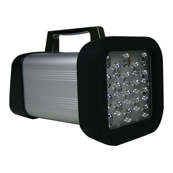
- Page 1 98805A LED Emission Model Stroboscope Digital Tachometer DT-365E Instruction Manual Be sure to read before use. Before use, please carefully read these safety precautions as well as instructions, and follow them for proper use. 800.561.8187 information@itm.com www. .com...
- Page 2 Safety Precautions Be sure to observe Before operation, maintenance and inspection, please carefully read this instruction manual and follow it for proper use. Please carefully read all information related to this unit and safety, and precautions before use. This instruction manual provides two grades of safety warnings: "Danger" and "Caution". Each of them is an important description related to safety.
-
Page 3: Table Of Contents
- Contents - Overview of this product Before use Checking the supplied items Peeling off the protection sheet Charging 2.3.1 Charging method 2.3.2 Indication of low battery voltage 2.3.3 Battery replacement Part names and functions Main unit Operation section Display 3.3.1 Part names 3.3.2... -
Page 4: Overview Of This Product
Refer to "4.4 External synchronous emission" for details 2 Before use 2.1 Checking the supplied items Check that the three items below are supplied. DT-365E x 1 Main unit Dedicated AC adapter x 1 AC adapter Instruction Manual This document x 1 800.561.8187... -
Page 5: Peeling Off The Protection Sheet
2.2 Peeling off the protection sheet Peel off the protection sheet on the operation section. Operation section Peel off the (transparent) protection sheet 2.3 Charging Be sure to charge the battery before initial use. Before charging, be sure to check that the power is turned OFF. -
Page 6: Indication Of Low Battery Voltage
If the battery-life duration becomes short, replace the battery with one that is specified. For a new battery, contact our dealer where you purchased this unit. (1) Remove the four screws on both ends of the bottom of the DT-365E main unit, and take out the built-in battery. -
Page 7: Part Names And Functions
3 Part names and functions 3.1 Main unit Super luminosity LED (6 lights) Operation section Signal jack port Power switch Dedicated AC adapter port 3.2 Operation section ④ ③ ⑤ ② ① Name Function description Power switch Turns the power ON/OFF. ①... -
Page 8: Display
3.3 Display 3.3.1 Part names Charging lamp Mode display B-CHG Numerical display ×2 Emission setting display ÷2 MODE 3.3.2 Number display •Indicates the setting value (of the emission count (frequency)) on internal oscillation emission. •Indicates the external signal frequency while on external synchronous emission. •Each setting value is indicated in the function setting mode. -
Page 9: Functions And Operations
4 Functions and operations 4.1 Power ON/OFF Press the power switch when the power is OFF to turn the power ON. When the power is turned ON, the model is indicated, followed by internal oscillation emission or external synchronous emission. Operation Display When the power is... -
Page 10: Emission And Mode Settings
4.2 Emission and mode settings Each press of the "MODE" key switches emission types and modes. Operation Display MODE External synchronous emission Internal oscillation emission (Emission count mode) (Phase mode) MODE MODE MODE Internal oscillation emission External synchronous emission Each press of this key (Emission duration mode) (Emission duration mode) MODE... -
Page 11: Internal Oscillation Emission
4.3 Internal oscillation emission 4.3.1 Display of internal oscillation emission Setting value Mode display Display showing internal oscillation emission 4.3.2 Emission count mode The emission count (frequency) can be set in the emission count mode (FPM). 4.3.2.1 Emission count setting Turn the dial in a CW direction to increase the emission count (frequency), and in a CCW direction to decrease it. -
Page 12: Changing The Emission Count (Frequency) To Double Or Half
4.3.2.2 Changing the emission count (frequency) to double or half The emission count (frequency) can be changed to double or half of the current setting value using the key operation on internal oscillation emission. 1) To change the emission count (frequency) to double of the current setting value Each press of the "x2"... -
Page 13: Emission Duration Mode
4.3.3 Emission duration mode The emission duration (ratio) can be set by 0.1º within the range between 0.1º/ 360º and 3.6º/ 360º in the emission duration mode (DUR). (The emission duration setting value shows the strobe emitting time by angle while a rotating object rotates one revolution (360º).) A longer emission duration increases the brightness, but a measured object appears to be moving. -
Page 14: External Synchronous Emission
4.4 External synchronous emission External synchronous emission is the function to emit a strobe flash in synchronization with the external trigger pulse. •To activate external synchronous emission, refer to "4.2 Emission setting". • You can set which edge of the external trigger pulse triggers emission, the rising edge or falling edge. Refer to "4.5.3 Trigger edge setting". -
Page 15: Emission Duration Mode
4.4.2 Emission duration mode The emission duration (ratio) can be set by 0.1º within the range between 0.1º/ 360º and 3.6º/ 360º in the emission duration mode (DUR). (The emission duration setting value shows the strobe emitting time by angle while a rotating object rotates one revolution (360º).) A longer emission duration increases the brightness, but a measured object appears to be moving. -
Page 16: Phase Mode
4.4.3 Phase mode Delay emission can be set within the input signal range between 60 fpm and 10,000 fpm. In the phase mode (PHA), the phase from the external trigger pulse entry to strobe flash emission can be changed by 0.1º using the dial within the range between 1º and 359º. When time is used for setting, a time longer than the emission cycle cannot be set. -
Page 17: How To Set The Delay
[Example 1] When setting the input frequency to 10 Hz (600 fpm), trigger edge to "rising", and delay angle to 36º 100ms(360°) 100ms(360°) External trigger pulse (Pulse entered from an external device to DT-365E) Strobe emission 10ms(36°) 10ms(36°) Frequency Frequency... -
Page 18: Function Mode
4.5 Function mode The following settings in the table can be configured in the function mode. Setting item Default setting value Function mode 1 Measurement range setting 120,000 Function mode 2 Trigger edge setting Function mode 3 Auto emission stop time setting 4.5.1 Moving to the function mode Turn the power ON while pressing the "MODE"... - Page 19 Operation Display Indicates alternately * Previous setting value Change the setting value MODE MODE Go to function mode 2 Go to function mode 2 800.561.8187 information@itm.com www. .com...
-
Page 20: Trigger Edge Setting (Function Mode 2)
When the trigger edge is set to "L-H" External trigger pulse (Pulse entered from an external device to DT-365E) Strobe emission * Delay time (time based on the delay angle setting value) When the trigger edge is set to "H-L"... -
Page 21: Auto Emission Stop Time Setting (Function Mode 3)
4.5.4 Auto emission stop time setting (Function mode 3) This setting is used to stop emission automatically when no operation is performed for a certain period of time. The available setting time is within the range between 0 min and 120 min, which can be changed by 1 minute. -
Page 22: External I/O (Phone Jack)
4.6 External I/O (phone jack) 4.6.1 Interface specifications On the DT-365E main unit: Phone jack (φ3.5mm - 2 poles) Use the φ3.5mm 2-pole phone plug for connection cables for input/output signals. Input signal plug port Output signal plug port 4.6.2 External trigger pulse input Connect the unit to external devices (sensors, etc.) to allow the strobe to emit light using the pulse... -
Page 23: Specifications
5 Specifications Model DT-365E Application Charging battery built-in model Emission count 60 to 120,000 fpm Setting accuracy ±0.02% Available to set to the range between 60 fpm and 120,000 fpm, or 60 fpm Measurement range setting and 12,000 fpm (Set in function mode 1) Measurement 60.0 to 3,000.0... -
Page 24: External Dimensions
Memory function •Saving the setting value when the power is OFF Available to set continuous emission, or set the time to stop emission by 1 minute within the range Auto emission stop between 1 min and 120 min. (Set in function mode 3) Built-in NiMH battery •Continuous emission time Approx. -
Page 25: Troubleshooting
7 Troubleshooting Symptoms Factors Causes Solution When the power is turned ON, The battery voltage is The battery is not "LLLLLL" is indicated, and no Charge the battery. low. charged. emission occurs. Replace the battery. Though the battery is fully Short battery life The battery capacity is If the problem has not been...
Need help?
Do you have a question about the DT-365E and is the answer not in the manual?
Questions and answers