
Related Manuals for Shimpo DT-326


Summary of Contents for Shimpo DT-326
- Page 1 DT-326 LED Stroboscope Operation Manual Read manual thoroughly prior to operation. Use instrument only after reading the complete manual. Follow all safety precautions.
- Page 2 Safety Precautions Please be sure to closely follow all safety precautions. Be sure to read the entire instruction manual thoroughly before initial set-up, operation and maintenance. The instruction manual provides two grades of safety warnings: "Danger" and "Caution". Follow these precautions. Danger "Danger"...
-
Page 3: Table Of Contents
Names and functions of the components ..........................................................................................................................4 4 4 4 DT-326 Unit ........................................................................................................................................ -
Page 4: Summary
By illuminating the rotating object with the DT-326, the moving object appears to remain still when the flashing rate of the DT-326 is equals the rotational speed of the target object. This allows inspection of rotating and moving parts, gears, shafts and others. -
Page 5: Product Inspection And Preparation
Product Inspection and Preparation 2.1 Confirmation of product packaging Confirm the following five parts in your DT-326 packaging: 1. One (1) LED stroboscope 2. Four (4) alkaline batteries (AA) 4. One (1) set of External input/output connector 3. One (1) AC Adapter (120V/240V, 50/60Hz) 3240-10P-C [HIROSE ELECTRIC CO., LTD.]... -
Page 6: Removal Of Protective Sheet
2.2 Removal of protective sheet Remove both protective sheets covering the operation panel and light source as shown below. Operation panel Protective sheet Light source 2.3 Installation of Battery Turn coin screws counter-clockwise to remove battery cover, and insert batteries in proper polarities as shown below: Coin screw Battery cover... -
Page 7: Names And Functions Of The Components
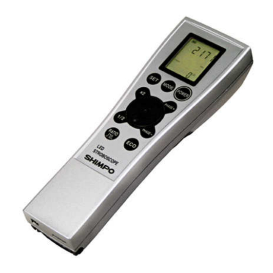
Names and functions of the components 3.1 DT-326 Unit Operation keys (9 totals) Flash rate/frequency setting dial LCD indicator display LED light source (3 totals) -
Page 8: Operation Panel
3.2 Operation panel Function Instructions POWER Power the unit on or off MODE Select Internal/ External/ Parameter mode of operation instruction Unit change, Select parameter setting item, Store setting value. ×2 Multiplies the flash rate/frequency by a factor of 2. Divides the flash rate/frequency by a factor of 2. -
Page 9: Lcd Display
3.3 LCD Display 3.3.1 Display Names and Descriptions Battery indicator Main data display Setting project Unit Auto Range Trigger Divider Edge Delay Deg Sub data Flash Time AveLastMinMax Ave Last Min ○ ○ ○ ○ 3.3.2 Main data display - Internal flashing mode: Displays flash rate. - External trigger mode: Display external trigger frequency. -
Page 10: Setting Project Display
3.3.5 Setting project display The following will be displayed, according to the mode of measure and *parameter settings Auto Range Auto Range Auto Range Auto Range Trigger Divider Trigger Divider Trigger Divider Trigger Divider Edge Delay Deg Edge Delay Deg Edge Delay Deg Edge Delay Deg Flash... -
Page 11: Function Instructions
Function Instructions 4.1 Power on/off Press “POWER” key to turn on unit. The unit will begin to flash in internal mode and the display will indicate the flash rate (FPM = flashes per minute). Operation Indication Power off Display will indicate the POWER POWER flash rate in internal... -
Page 12: Internal Flashing Mode
Internal flashing mode 4.3.1 Instruction for Internal flashing mode Battery power Flashing time (Hz shown) indication setting Flash indicator Auto Range Unit (min or Hz) Trigger Internal flashing Edge Deley Deg “Min” means Eco mode Flash Time mode Ave Last Total phase shift angle ○... -
Page 13: Flash Rate And Frequency "Internal Mode
4.3.4 Flash rate and frequency “Internal Mode” Set the flash rate (frequency) by turning the center dial. Clockwise: Increase Counter-clockwise: Decrease For small adjustments, turn the dial slowly. For large adjustments, rotate the dial quickly. The flash rate and resolution differs according to measuring range. Refer to section 4.5.1 for details. Notes for setting the flash rate One function of a stroboscope is to provide a “Frozen”... -
Page 14: Multiply / Divide By 2 Function
4.3.5 Multiply / Divide by 2 Function The flash rate or frequency can be doubled or halved by the”x2” and “½” keys on the operation panel. 1) Doubling the flash rate (x2) Press “x2” key to multiply the current flash rate by a factor 2 until the max flash rate is reached. Operation Indication FLASH... -
Page 15: Phase Shift (Angle)
4.3.6 Phase Shift (Angle) Once "Frozen" virtual image is achieved via FPM=RPM, the phase shift function can advance or delay the flash so that the image appears to be slowly rotating CW or CCW incrementally. Press “PHASE+” key or “PHASE-“ key to increment or decrement the phase shift angle by 3° . The display will show the cumulative angle of the phase shift. - Page 16 Press the “RATIO” key. The current mode will start blinking for 5 seconds allowing modification at this point. Operation Indication External trigger mode Internal flashing mode RATIO FLAS Press and release Auto Range Auto Range Trigger Trigger Edge Deley Deg Edge Deley Deg Flash Time...
- Page 17 Operation Expression FLASH PHASE+ Press and release … Auto Range Auto Range Auto Range Trigger Trigger Trigger Edge Deley Deg Edge Deley Deg Edge Deley Deg PHASE+ Flash Time Flash Time Flash Time Ave Last Min Ave Last Min Ave Last Min ○...
-
Page 18: External Trigger Mode
4.4 External Trigger Mode This mode allows synchronization of the FPM with external signal input such as a sensor. See section 4.7 for details. Parameter settings are possible, like phase shift, delay time, flash duration, edge trigger. 4.4.1 External trigger mode: LCD display information Battery Indicator Frequency of external trigger input Light off... -
Page 19: Delay Time" Setting
4.4.2.1 “Delay time” setting This can be set to 0~999 msec with a resolution of 1 ms. The internal calculation time of the unit is 60us, which results in the actual delay time being (Setting delay time) + 60us. The unit will begin flashing after the 1 trigger pulse as detected per timing chart below. - Page 20 Press "PHASE+" key to select the delay time setting. Turn dial CW to increase and CCW to decrease. Button operation Expression Auto Range Auto Range Auto Range Trigger Trigger Trigger Edge Deley Deg Edge Deley Deg Edge Deley Deg Flash Time Flash Time Flash Time Ave Last Min...
-
Page 21: Delay Angle Setting
The actual delay time is as follows: Delay angle setting × Period of External Input + approx. 60us (Built-in) 360° While the DT-326 does not flash at the 1 trigger pulse as shown below in the timing chart. [Example] Trigger: Positive edge Delay angle: 36°... -
Page 22: Units Of Measure- Changing From Fpm To Hz
Delay Angle setting will decrease from 359° (Max) t o 0° (Min) value for counter clockwise. The setting s will eventually go to 0° as when angle decreases from 359 ° . ・・・・ Auto Range Auto Range Auto Range Trigger Trigger Trigger Edge... - Page 23 4.5 Parameter Setting Instruction Press “MODE” until the LCD displays “P” (Parameter setting mode). Press the “SET” key to cycle between the various parameter settings available (range, trigger edge, delay time, and LCD backlight). For more information regarding the various parameter settings, please refer to sections 4.5.2 through 4.5.4 below.
-
Page 24: Measurement Range Setting
4.5.1 Measurement range setting The DT-326 has a selectable measuring range, which can be set in the Parameter mode setting. The range and resolution of this setting will be different for each measuring range, as indicated in the table below. - Page 25 Operation Expression FLASH PHASE+ Press and release FLASH PHASE+ Auto Range Auto Range Trigger Trigger Edge Deley Deg Edge Deley Deg Flash Time Flash Time Ave Last Min Ave Last Min ○ ○ ○ ○ ○ ○ ○ ○ Measuring range set to Measuring range set to “1 –...
-
Page 26: Trigger Edge Setting (External Mode)
Trigger 4.5.2 Edge setting (External Mode) Select Positive or Negative edge. Examples: -When trigger edge setting is set to “Positive Edge”, the flash will occur on the leading edge of the input pulse (when delay setting is zero). External Pulse signal from machine/sensor Stroboscope flash *Delay time (based on the delay settings of parameter) - Page 27 Press the “SET” key to cycle to the Trigger Edge setting parameter mode. To set the trigger edge as “Down edge”, press “PHASE -“key or turn the dial clockwise. To set the trigger edge as “Up edge”, press “PHASE +” key or turn the dial counter clockwise. Operation Expression FLASH...
-
Page 28: Delay Setting
4.5.3 Delay setting Delay time and angle setting will allow the flash to be delayed after an external pulse is sensed by the unit. The Parameter setting mode: Press “PHASE +” and “PHASE -“ key, to select between delay time and delay angle. 4.5.3.1 Delay time setting Selecting Delay time from an external pulse input to LED flashing can be set in the range of 0 –... - Page 29 4.5.3.2 Delay angle setting The delay angle can be set from 0° to 360° by 1° in crements. Delay angle setting increases as the dial turns right, and decreases as it turns left. Delay angle events to zero when set below 0° (min) or 360° (max). Operation Expression Auto Range...
-
Page 30: Back Light Setting
4.5.4 Back light setting Press “SET” key in Parameter mode to enable this mode. Turning off the backlight will conserve battery power. For more information regarding the automatic settings of the backlight, see section 4.6. Press “PHASE +” key to turn on the backlight. Press “PHASE -” key to turn off the backlight Button operation Expression PHASE+... -
Page 31: Connector Of External Input/Output
OUT_COM Universal interface of External pulse output (no connection) Ground electrode of frame work Connector type DT-326 side: 3260-10S3 (55) [HIROSE ELECTRIC CO., LTD.] Accessory: 3240-10P-C [HIROSE ELECTRIC CO., LTD.] 4.7.2 External Pulse Input The unit can be operated and controlled by an external signal, from either a sensor or a machine signal like an output from a printing press, re-winder or others. -
Page 32: Option Cable- Input/ Output Cable Adaptor
4.7.4 Option Cable- Input/ Output cable adaptor Because the connector of the unit is not separate from input and output signal, the option cable adapter separated I/O is provided for easy connection. Input (Sensor) Output (Other device) 100mm (4”) 1,780mm (70”) -
Page 33: Specifications
Specifications Model Number DT-326 Units of measure FPM (flashes per minute) or Hz (frequency) Measuring range 1 - 2,000Hz 60 - 120,000 FPM Accuracy +/-0.02% (at 73° F [23° C]) Resolution Unit; Measuring 0.01Hz of flash rate range: setting in 1-200 Hz 0.1Hz... - Page 34 Display 6 digits (main), 5 digits (sub) “LOW BAT”, “Setting item”, “Unit” Back light Yellow green LED Flashing part Flash Source Super High Brightness White LED 5500K (typ) Life time More than 1500 hours (approx. 5X10 times at 6000 FPM) Luminance Normal 20cm | 6,000FPM...
-
Page 35: Dimensions
Dimensions Side 70mm 60mm (2.36”) (2.76”) 1/4-20UNF Depth 8mm (0.32”) Front 36mm Back 52mm (0.12”) (1.42”) (2.05”) Bottom...
Need help?
Do you have a question about the DT-326 and is the answer not in the manual?
Questions and answers