Table of Contents

Related Manuals for Shimpo FGV-0.5XY


Summary of Contents for Shimpo FGV-0.5XY
- Page 1 Digital Force Gauge FGV - 0.5/1/2/5/10/20/50/100/200 XY Instruction Manual Please read the entire manual before using your gauge. UNIT POWER PEAK ZERO MEMORY ZERO PEAK MEMORY UNIT POWER REVERSE FGV-10XY 10.00lb/5.000kg/50.00N NIDEC-SHIMPO CORPORATION...
- Page 2 Do not open, repair, or attempt to modify plugs, and not the cables. your FGV-XY. Unnecessary tension on the power chord may Please contact your Shimpo dealer for information create a shock or fi re hazard. regarding repairs and modifi cations.
- Page 3 Operate your FGV-XY within 35 ~ 85% RH. once per year. Use of your FGV-XY outside this humidity range may cause malfunctions or damage. Contact your Shimpo dealer for information regarding calibration. Caution Do not press the buttons on the FGV-XY Do not apply side loads or torque to your FGV-XY.
-
Page 4: Table Of Contents
Table of Contents 1. Product Features 5.6 Memory 2. Standard Accessory Checklist 5.6.1 Setting the Memory Mode 3. Parts of your FGV-XY 5.6.2 Recording Memory Data 3.1 Main Unit 5.6.2.1 Continuous Mode 3.2 Display 5.6.2.2 Single Mode 3.2.1 LCD Sections 5.6.2.3 Standard Mode 3.2.2 Numeric Display 5.7 Reviewing Memory Data... -
Page 5: Product Features
1. Product Features ●Nickel – Hydrogen battery allows for long periods of use. → 4.1 Battery ●Data can be downloaded to PC via USB. → 5.9 USB Communication ●1000 points of data storage. → 5.6. Memory ●Comparator feature for pass/fail testing. →... -
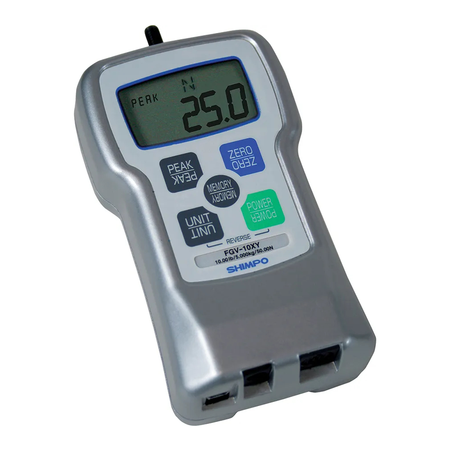
Page 6: Parts Of Your Fgv-Xy
3. Parts of your FGV-XY 3.1.Main Unit PEAK ZERO MEMORY UNIT POWER REVERSE FGV-10XY 10.00lb/5.000kg/50.00N Sensor Shaft Apply your force in line with this threaded shaft. Use the included attachments for a your testing application. Display LCD screen is unit's main information display, PEAK Press PEAK to change measuring modes UNIT... -
Page 7: Display
3.2 Display 3.2.1 LCD Sections Unit Type Comparator Indicator Max/Min Measurement Value Peak Mode Indicator 3.2.2 Numeric Display The default setting for the four digit display shows compression loads as a positive force and tension loads as a negative force. To reverse these settings, showing compression loads as negative and tension loads as positive, see section 4.5 for setting f01. -
Page 8: Setup
Use only the AC adapter supplied with your FGV-XY. Do not use a third party adapt- Do not charge with er. Doing so could cause a fi re or shock hazard. Contact your Shimpo dealer if you non-standard AC adapter. -
Page 9: Tracking
4.4 Tracking The FGV-XY uses a load cell and strain gauge as its force sensor. The sensor is affected by environmental changes such as temperature and humidity. The Tracking function, which is active by default, helps to negate the effects of these changes. Tracking can cause errors when measuring very small forces. -
Page 10: Measurement Polarity: F01
4.5.1 Measurement Polarity: f01 This function allows you to change whether compression is shown as a positive or negative force. Once the compression display has been changed, the tension display will then read as the opposite of the compression. Press UNIT to change the setting, PEAK to save and move to the next function, or ZERO to save and fi... -
Page 11: Rs-232C Baud Rate: F04
4.5.4 RS-232C Baud Rate: f04 This function allows you to change the RS-232C communication rate. The available baud rates are 2400, 4800, 9600, and 19200 bps. Press UNIT to change the setting, PEAK to save and move to the next function, or ZERO to save and fi nish. Key Operation Display 9600... -
Page 12: Reversing The Display
4.6 Reversing the Display If you have mounted your FGV-XY upside down, or are holding the unit upside down during measurement, the display may be reversed for readablity. Key Operation Display Turn Power Off ZERO ZERO PEAK Standard Display Reversed Display Reversed Display UNIT POWER... -
Page 13: Measuring Mode
5.2 Measuring Mode The two measurement modes available are Standard and Peak. 5.2.1Standard Measuring Mode This mode shows the current force applied, tension/compression, on the sensor shaft. 1. Turn on the FGV-XY by pressing POWER. 2. Press ZERO to tare the gauge. 3. -
Page 14: Comparator
5.5 Comparator 5.5.1 Compatrator Overview The Comparator function allows you to create conditions for Go/No Go testing. A high(HI), and low(LO) force limit may be set so that the FGV-XY's display will show when a measurement is not within the HI and LO settings. In addition, the output port will respond relative to the display. -
Page 15: Setting Lo Limit
5.5.4 Setting LO Limit The procedure to set the HI limit is used to set the LO limit. The absolute value of the LO limit may never be higher than Section 5.5.3 contains this information. the absolute value of the HI limit. LO limit setting mode Operation PEAK... - Page 16 Memory terms defi ned: Measurement value: The current displayed value in Standard mode. Positive maximum value (+MAX): Maximum value in the positive direction. Negative maximum value (-MAX): Maximum value in the negative direction. Positive minimum value (+MIN): Minimum value in the positive direction. Negative minimum value (-MIN): Minimum value in the negative direction.
-
Page 17: Setting The Memory Mode
5.6.1 Setting the Memory Mode Turn the POWER off. Press PEAK and hold, then press and release POWER. The display will show the HI Comparator limit. Press PEAK twice to display the current memory mode. Press UNIT to cycle the Memory mode. Press MEM to save and exit. -
Page 18: Recording Memory Data
5.6.2 Recording Memory Data The following procedures explain how to activate memory recording for each memory mode. 5.6.2.1 Continuous Mode 1. In continuos measurement mode, press MEM to start the recording. The letter M will appear and start blinking. Press M to stop the recording. -
Page 19: Reviewing Memory Data
5.7 Reviewing Memory Data 5.7.1 Continuous Mode Memory 5.7.1.1 Accessing Memory Data 1. Turn the POWER off. Press MEM and hold, then press and release POWER. Release MEM when you see "CNT" on the display. The unit will alter- nate between showing the data block number, and the recorded measurement value of that block. 2. -
Page 20: Statistics Data
5.7.1.2 Statistics Data 1. When in memory mode, UNIT will cycle through the available statistics data. 2. Each press of UNIT will switch between the following items: positive maximum value, negative maximum value, positive minimum value, nega- tive minimum value, positive peak value, negative peak value, average value, standard deviation. 3. -
Page 21: Single Mode Memory
5.7.2 Single Mode Memory 5.7.2.1 Accessing Memory Data 1. Turn the POWER off. Press MEM and hold, then press and release POWER. Release MEM when you see "SIg" on the display. The unit will alternate between showing the data block number and the recorded measurement value of that block. 2. -
Page 22: Statistics Data
5.7.2.2 Statistics Data 1. When in memory mode, UNIT will cycle through the available statistics data. 2. Each press of UNIT will switch between the following items: positive maximum value, negative maximum value, positive minimum value, negative minimum value, average value, standard deviation. 3. -
Page 23: Standard Mode Memory
5.7.3 Standard Mode Memory 5.7.3.1 Accessing Memory Data 1. Turn the POWER off. Press MEM and hold, then press and release POWER. Release MEM when you see "STd" on the display. The unit will alternate between showing the data block number, and the recorded measurement value of that block. 2. -
Page 24: Statistics Data
5.7.3.2 Statistics Memory Data 1. When in memory mode, UNIT will cycle through the available statistics data. 2. Each press of UNIT will switch between the following items: positive maximum value, negative maximum value, positive minimum value, negative minimum value, positive peak value, and negative peak value. 3. -
Page 25: Clearing All Memory
5.8.2 Clearing All Memory 1. While viewing the last memory point, press and hold ZERO. 2. The display will show "nonE". 3. All memory has now been cleared, which returns the unit to standard measurement mode. Key operation Display Memory block number Turn power off (Push for 5 seconds or more) ZERO... -
Page 26: External Data Port
HR12-10RC-10SDL, by Hirose, is the output connector. We recommend HR12-10PCAE300 with 10 conductor Analog + shielded cable to make your own. Analog GND Please call your Shimpo dealer for information regard- RxD (RS-232C Received Data) ing optional cables and accessories. Host --> FGV Digital GND... -
Page 27: Rs232C Communication Commands
6.2.2 RS232C Communication Commands Typical Host -> FGV commands. "cr"means carriage return. Commands Content Response Explanation of Response AA cr Tare Tare AA cr AB cr Cancel data transmission Cancel data transmission AB cr AC cr Switch to positive peak mode Switch to positive peak mode AC cr AD cr... -
Page 28: Connection Between Fgv And Host
6.2.3 Connection between FGV and Host Host Data Ouput Port 9 pin serial connection Without the connection between the Digital GND and pin 5, RS-232C communication will not work. Digital GND Connection Detection 6.3 Analog Output ± 1V Analog Output The output voltage's polarity corresponds to the polarity shown on the display during standard measurement mode. -
Page 29: Frequently Asked Questions
Please contact your Shimpo dealer regard- ing battery replacement, and repair. Do you have CAD or techinical draw- CAD and technical drawings are availabale Please contact your Shimpo dealer for infor- ings available? for the FGV-XY. mation regarding CAD and technical draw- ings. -
Page 30: Support
8.2 Warranty Nidec-Shimpo Corp. warrants, to the original purchaser of new products only, that this product shall be free from defects in workmanship and materials under normal use and proper maintenance for one year from the date of original purchase. See fi nal page for full warranty disclosure. - Page 31 Measurement Attachments (standard accessories) The following drawing is for the attachments included with the FGV-5 ~ 50XY (M6). Please contact your Shimpo dealer for information on the attachments included with 0.5, 1, 2, and 200 models. Flat Head: 12 Chisel: 70°...
- Page 32 Shimpo Instruments reserves the right to satisfy warranty LIMITED EXPRESS WARRANTY Shimpo Instruments warrants, to the original purchaser obligation in full by reimbursing Buyer for all payments of new products only, that this product shall be free made to Shimpo Instruments, whereupon, title shall pass to Shimpo Instruments upon acceptance of return goods.
Need help?
Do you have a question about the FGV-0.5XY and is the answer not in the manual?
Questions and answers