
Related Manuals for Shimpo DT-5TS


Summary of Contents for Shimpo DT-5TS
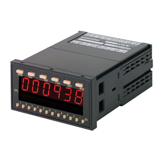
- Page 1 DT-5TXR / DT-5TS DIGITAL PANEL MOUNT TACHOMETER Instruction Manual GlobalTestSupply www. .com Find Quality Products Online at: sales@GlobalTestSupply.com...
-
Page 2: Table Of Contents
Measurement/Monitoring)........9 Mode -03- (Process Time Measurement).... 10 “How to Operate” Teaching Feature .....10 Congratulations on your purchase of a Shimpo DT-5TXR or DT-5TS digital panel mount tachometer. Whether Setting High and Low Limits ......... 11 measuring RPM or a complex function, we trust you will enjoy many years of professional results. -
Page 3: Standard Accessories
Never use wet hands when connecting or disconnecting a sensor or checking the unit. Items included with the DT-5TXR or DT-5TS are: • Mounting adapter, 2 pieces (attached) Always use the correct voltage (AC type: 85- • Mounting screw, 2 pieces (attached) 264VAC, DC type: 9-35VDC). -
Page 4: Display And Keypad
Display and Keypad s ’ s t i Secondary Display B Secondary display Negative Sign/Decimal Point Button Negative sign setting/decimal point shift Secondary Display A Secondary display Comparator Indicator Indicates comparator condition GlobalTestSupply www. .com Find Quality Products Online at: sales@GlobalTestSupply.com... -
Page 5: Rear Panel And Terminals
LED display will light up. diagram 1 Sensor Connection Use the chart below to determine how to connect the DT-5TXR/DT-5TS to Shimpo sensors: SENSOR TERMINAL NUMBER FREQUENCY or RPM RANGE OPERATION TEMPERATURE FILTER TYPE –... -
Page 6: Panel Installation
4. Hold the panel meter in a horizontal position, insert it into the cut-out and press against gasket (diagram 5). 5. Replace the two mounting adapters (diagram 6). 6. The DT-5TXR/DT-5TS is secured on the panel by using the two mounting screws (provided) (see diagram 7). diagram 4... -
Page 7: Operation
NOTE: If a mistake is made entering any number, simply press the BACKSPACE button to erase the last digit on the primary display. Mode -01- (RPM or Rate Measurement) The following parameters must be set in mode -01- so that the DT-5TXR/DT-5TS will display the correct readings: FACTORY SETTING PARAMETER... - Page 8 Mode -01- (RPM or Rate Measurement) continued Set the parameters in mode -01- as follows: 7. Press the PAR button; the display will reflect: 1. Press the PAR button; the display will indicate: Parameter 4 is now showing on the primary display (1.0 second [factory setting]).
-
Page 9: Mode -02
Mode -02- (Elapsed Time Measurement/Monitoring) The following parameters must be set in mode -02- so that the DT-5TXR/DT-5TS will display the correct readings: FACTORY SETTING PARAMETER DESCRIPTION RANGE DISPLAY MEANING Pulses p i t u – _ _ 0001 1 p/r... -
Page 10: Mode -03- (Process Time Measurement)
Mode -03- (Process Time Measurement) The following parameters must be set in mode -03- so that the DT-5TXR/DT-5TS will display the correct readings: FACTORY SETTING PARAMETER SETTING RANGE DISPLAY MEANING Hours, minutes, seconds 00:00:00 0:00 Hundreds of a second 0:00... -
Page 11: Setting High And Low Limits
NOTE: The DT-5TXR provides relay or transistor closures (see section “Modules Available for DT-5TXR” on page 15). Setting Functions The DT-5TXR/DT-5TS has a variety of functions that can be programmed to further customize the meter. Listed below are the available functions:... -
Page 12: Memory Feature
Function 4 is now showing (factory setting). The function of the MEM button is to aid the NOTE: This function is mainly used with mode -01- DT-5TXR/DT-5TS to memorize and display through the only. secondary displays the maximum and minimum value of 8. -
Page 13: Setting Examples
Set parameter 6 according to the sensor being used. the belt in ft/m at all times. MODE -02- As stated in the previous example, the DT-5TXR/DT-5TS units are fully scalable. This is true for not only rate measurement but also time measurement. The following is an elapsed time measurement/monitoring example. - Page 14 This requires a timer to be able to start counting then stop and display the actual process time. The DT-5TXR/DT-5TS has a MODE for this application (and DT-5TS/5TX similar ones) where it can measure the ON time of a signal...
-
Page 15: Modules Available For Dt-5Txr
Modules Available for DT-5TXR DT-5TXR with DOP-CPTR Module A variety of modules are available to provide an array of output and input options when using the DT-5TXR. DT-5TXR-CPTR The model DT-5TXR-CPTR provides three “C” type relays that Most of the modules have either a “T” or “C” suffix in can be used for setting two “set points”, one high and the part number. -
Page 16: Dop-Trtr Module
The different outputs are not achieved through DT-5TXR with DOP-TRTR Module programming, but by making the proper connections. DT-5TXR-TRTR The DT-5TXR panel meter with the DOP-TRTR The connections for the DOP-FVTR module are as follows: module provides two high set points (limits) and two low set points in addition to the normal GO signal output. - Page 17 DT-5TXR-FVTR/DT-5TXR-FVC (continued) Instructions to set the analog output characteristics are as follows: 1. Press the FUN button eleven times; the display will reflect: 5. Press the FUN button again; the display indicates: The display shows that the maximum RPM is set for The display reflects the factory setting.
-
Page 18: Dop-Bcd Module
DT-5TXR with DOP-BCD Module DT-5TXR-BCD The model DT-5TXR-BCD combination satisfies PCs and PLCs The waveforms show that when the ENABLE function is that require a BCD (parallel) signal. The DOP-BCD module LO, the BCD output data goes to a high impedance state can be configured with a negative logic output (0=HI to facilitate the selection of one unique DT-5TXR-BCD unit and 1=LO) or a positive logic output (0=LO and 1=HI),... -
Page 19: Dimensions And Specifications
0.66 lb (300 g) 5.27" L x 3.78" W x 1.89" H ( 134 mm x 96 mm x 48 mm) Dim ensions Warranty 1 year Sensors , modules OPTIONAL ACCESSORIES DT-5TS MODEL Mode r e t Elapsed Time Process Time Display Range... -
Page 20: Troubleshooting
This warranty shall not be effective if the product has been subject to overload, misuse, negligence, or accident, or if the product has been repaired or altered outside of Shimpo Instruments’s authorized control in any respect which in Shimpo Instruments’s judgment, adversely affects its condition or operation.
Need help?
Do you have a question about the DT-5TS and is the answer not in the manual?
Questions and answers