Advertisement
Quick Links
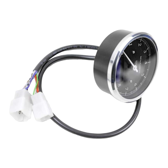
Operating and installation guide
motoscope Classic, Chronoclassic and
motoscope Classic speedo
starting at serial no. 00030961
Suchen Sie die deutsche Bedienungsanleitung?
http://motogadget.com/media/downloads/manual/msc_chc_manual_de_4.8.pdf
ABE
KBA 91262
________________________________________________________________
HW 2.1
SW 4.03
Manual 4.8_k
1
Advertisement

Related Manuals for motogadget motoscope Chronoclassic


Summary of Contents for motogadget motoscope Chronoclassic
- Page 1 Operating and installation guide motoscope Classic, Chronoclassic and motoscope Classic speedo starting at serial no. 00030961 Suchen Sie die deutsche Bedienungsanleitung? http://motogadget.com/media/downloads/manual/msc_chc_manual_de_4.8.pdf KBA 91262 ________________________________________________________________ HW 2.1 SW 4.03 Manual 4.8_k...
- Page 2 Thank you very much for purchasing a high quality product from motogadget. Please read the following information and recommendations carefully and follow these instructions for installation and usage of the instrument. No liability is assumed by motogadget for damage or defects resulting from negligence or failure due to following the operating manual.
-
Page 3: Exclusion Of Liability
1 Review of delivery All products from motogadget are thoroughly checked to ensure that they are faultless when dispatched. Please check received goods for possible transport damage. If you find any damage or other deficiencies please contact us immediately. For returns or replacements we refer to our general terms of business and delivery published on www.motogadget.com. - Page 4 3.1 Feature Overview Features Measuring Range Analog display (indicator) for rpm or road speed, depending 0–8 krpm / 10 krpm / 14 krpm on model 0–200 km/h or mph Speedometer 0–350 km/h or mph up to 999.99 km or mi Day trip meter Total distance (adjustable) up to 250.000 km or mi...
-
Page 5: Quick Start
Mounting hardware such as cable ties, connectors, heat shrink tubing, soldering iron We recommend use of wiring diagrams for electrical connection. If you don’t use the motogadget all-purpose bracket you will need a stable mounting bracket for the instrument. The speedometer sensor is already equipped with a connecting cable (length 1.5 meters) so that the sensor can be connected to the front or rear wheel. -
Page 6: Installation Of The Instrument
6 Safety Instructions for Installation and Connection • Ensure your vehicle is standing firmly on the ground before beginning installation works. • Disconnect the connector cable from battery minus to the on-board electrical system. • In your own interest and in the safety interest of third persons, ensure a good and solid mount for all mounting parts. - Page 7 8.1.1 Assignment and Color Code 6-pin Connector for the motoscope classic Function Cable Color Connector Plus of the switched on-board power Power supply supply, protected by a 1A fuse. Black Power supply Ground leads to the ignition coil, terminal 1...
- Page 8 Before beginning installation work, the ground cable has to be disconnected from the battery. The motoscope classic works on on-board power supplies with 9-18VDC. Operating the device on a on-board power supply without a battery connected is not intended by design and is not recommended.
- Page 9 Two wire hall sensors are not compatible to the motoscope . Connect the orange cable of the motoscope directly to the speed sensor signal cable. You will have to use the (included) motogadget speedometer sensor if no speedometer signal can be detected.
- Page 10 Activate the on-board power suply. The display should light up and show the startup display (motogadget logo). If this is not the case, please deactivate the ignition and systematically recheck all connections of the instrument and the sensor connector cables.
- Page 11 11.2 The analog Display with pointer Depending on the model, the device shows rpm or ground speed. The models with the ground speed scale have to have the value of Damp at 9 in the MOTOR setup parameter. The value of SCL has to be 10K.
- Page 12 11.3.7 Temperature Gauge T1, Optional Air (AIR) or Water Temperature (H2O) This value represents the actual air or water temperature as soon as it reaches the measuring range of the sensors. Out of range is indicated by "---" . In setup, upper and lower limits (minT, maxT) can be set. These values have to be inside the measuring range.
- Page 13 12 The Setup Operation and setup of the motoscope classic is conducted via one push-button. For this reason, the setup is organised in "levels". Push-button activation for different durations is used for toggling and selecting these levels. The activation time of the push-button is indicated by 1, 2 or 3 horizontal lines on the display.
- Page 14 Please refer to the table in the appendix for the right outer tire diameter (alternative download at www.motogadget.de). The ABE is only valid with a correct value from this table. If your tires can not be found in the table, please measure the outer diameter of the tire (of the wheel the speedometer sensor is attached to) with a piece of cord.
- Page 15 ImpENG This feature determines the number of ignition impulses per crankshift revolution. A level 1 push- button action toggles the next value, level 3 exits the menu and switches back to the PARAM main menu. If your vehicle is equipped with multiple ignition coils, only the impulses from the coil with the signal cable attached (i.
- Page 16 Test the display for accuracy. In threshold ranges, the instrument might temporarily display the wrong gear. If the result is overall inconsistent, the teaching process has to be repeated. Please do not teach the gears to your device on public roads but on a suitable, blocked area. The measuring is made at your own risk.
-
Page 17: Troubleshooting
12.6 The Subitem RESET (Reset Features) RESET Reset of all saved values to 0 or to factory default resp.. Selection of "yes" deletes all values accumulated during operatioon as well as the total trip value. Internally, the instrument is set to a "new condition". Selection of "yes"... - Page 18 - print and fill the repair return form (refer link below) and attach it http://motogadget.com/media/downloads/support/form_return_repair.pdf - Not prepaid shipments will be rejected. - The Shipment to motogadget is carried out by your own risk - you are responsible for a sufficient insurance. - Make sure the package is adequate.
- Page 19 15 Appendix 15.1 Connection Diagram (System Connector, 6-Pin and 9-Pin)
- Page 20 15.2 Overview: Operation with the Menu Push-Button...
- Page 22 15.3 Table of Tire Circumferences front wheel tire sizes and circumference settings 16´´ tire inner diameter tire size circumference (mm) tire size circumference (mm) 100/90-16 1770 130/70-16 1776 110/90-16 1824 130/90-16 1933 120/80-16 1806 150/80-16 1951 120/90-16 1878 17´´ tire inner diameter tire size circumference (mm) tire size...
Need help?
Do you have a question about the motoscope Chronoclassic and is the answer not in the manual?
Questions and answers