Advertisement
Operating and installation guide
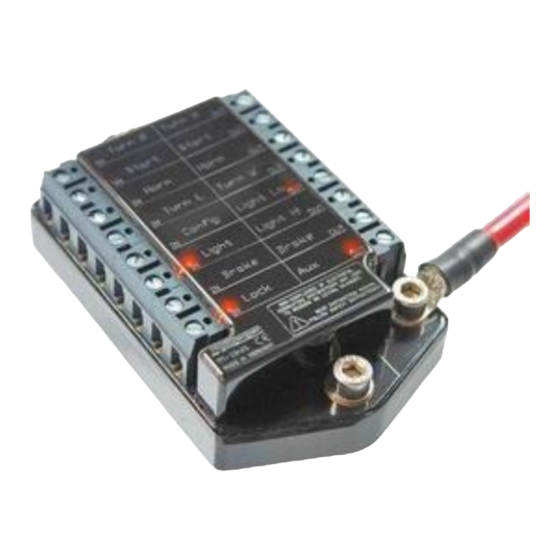
digital control device m-Unit V.2
valid from serial no. 00005841
(see the serial sticker at the device)
Suchen Sie die deutsche Bedienungsanleitung?
http://motogadget.com/de/elektrik/elektronische-steuerbox-m-unit/downloads.html
_______________________________________________________________
HW V2.1
SW V2.0
Manual V3.6_k
0
Advertisement
Table of Contents

Subscribe to Our Youtube Channel
Related Manuals for motogadget m-Unit V.2


Summary of Contents for motogadget m-Unit V.2
- Page 1 Operating and installation guide digital control device m-Unit V.2 valid from serial no. 00005841 (see the serial sticker at the device) Suchen Sie die deutsche Bedienungsanleitung? http://motogadget.com/de/elektrik/elektronische-steuerbox-m-unit/downloads.html _______________________________________________________________ HW V2.1 SW V2.0 Manual V3.6_k...
- Page 2 Thank you very much for purchasing a high quality product by motogadget. Please read the following information and recommendations thoroughly and follow these instructions during installation and use of the instrument. No liability is assumed by motogadget for damage or defects resulting from negligence or failure to follow the operating and installation guide.
-
Page 3: Exclusion Of Liability
1 Review Of Delivery All products from motogadget are thoroughly checked to ensure they are completely fault free when dispatched. Please check the received goods immediately for possible transport damage. If you find any damage or other deficiencies, please contact us immediately. -
Page 4: Safety Instructions
4 Safety Instructions • PRIOR ELECTRICAL CONNECTION OF THE DEVICE AND GENERALLY PRIOR TO ANY WORK AT THE VEHICLES ELECTRICAL SYSTEM BATTERY MUST BE DISCONNECTED COMPLETELY. THEREFORE KEEP THIS ORDER: DISCONNECT AT FIRST THE NEGATIVE TERMINAL THEN POSITIVE TERMINAL. RECONNECTION ACT IN THE REVERSE ORDER. •... - Page 5 The device is completely moulded and resistant against water, heat, cold and vibrations. Micro- processor operated and supervised circuits guaranty highest reliability. Current flow of each circuit is measured with high accuracy. In case of a failure like a short-circuit or overload the concerning loop will be shut down in a split second.
-
Page 6: Mechanical Installation
Kill switch The running engine can be stopped in three different ways: a) engine start button double click Pressing the button again after engine stop will crank and start the engine in normal way. b) Connecting a separate kill switch or push button at the "config" terminal. If a push button is used the engine is stopped if push button is shortly pressed. -
Page 7: Safety Functions
If cables with a lesser diameter than indicated in Chapter 7.4 are connected (e. g. motogadget instruments or the m-lock), they have to be protected by the included fusible links. 7.4 Cable Routing Recommendations Cables used in vehicles must be suitable for this application. - Page 8 In addition, the cables have to be properly isolated, especially in places where mechanical wear can take place. We recommend solder joints. For fastening the cables we recommend cable ties of synthetic material. To prevent corrosion from the m-unit terminals you must apply terminal grease to the screws and into the cable inlets.
-
Page 9: Handle Bar Controls
7.7 Handle Bar Controls Three different types of handle bar controls are compatible with m-Unit. The particular type which will be used with m-unit must set in the setup menu. Configuration A) – 5-push button controls turn lights left push button turn lights right push button low beam / high beam... - Page 10 Simplified vehicle circuit diagramm The circuit diagram below shows a simplified vehicle wiring loom.
- Page 11 Simplified vehicle circuit diagramm with m-Button (optional accessory) The circuit diagram below shows a simplified vehicle wiring loom with use of the m-button. Therefore 6 wires do not apply, because only one cable is needed to connect handle bar controls with m-unit.
- Page 12 Ignition Lock If m-Lock from motogadget will be applied instead of a conventional ignition lock the m-lock switching output (brown cable) can be connected directly to the m-Unit input „lock“. The delivered m-Lock relay is not applicable.
- Page 13 8 Setup 8.1 Layout Device setup is structured in 7 menus (1-7) with particular options (A-F) as follows: Menu 1 – Brake light configuration A) standard (continuous light) > default setting B) fade in and fade out C) flashing D) 8 times flashing and continuous light E) 2 times flashing;...
-
Page 14: Starting The Setup
8.2 Navigation Through Setup Menu All LED at input side represent menu 1 - 7. All LED at the output side represent option A - F. Flashing LED shows the actual chosen menu or option. A short push button operation (less than 1 second) changes to the next menu or option. A long push button operation (2s) change between menu and options. -
Page 16: Troubleshooting
- print and fill the repair return form (refer link below) and attach it http://motogadget.com/media/downloads/support/form_return_repair.pdf - Not prepaid shipments will be rejected. - The Shipment to motogadget is carried out by your own risk - you are responsible for a sufficient insurance. - Make sure the package is adequate.
Need help?
Do you have a question about the m-Unit V.2 and is the answer not in the manual?
Questions and answers