
Related Manuals for Moore Industries TDZ2


Summary of Contents for Moore Industries TDZ2
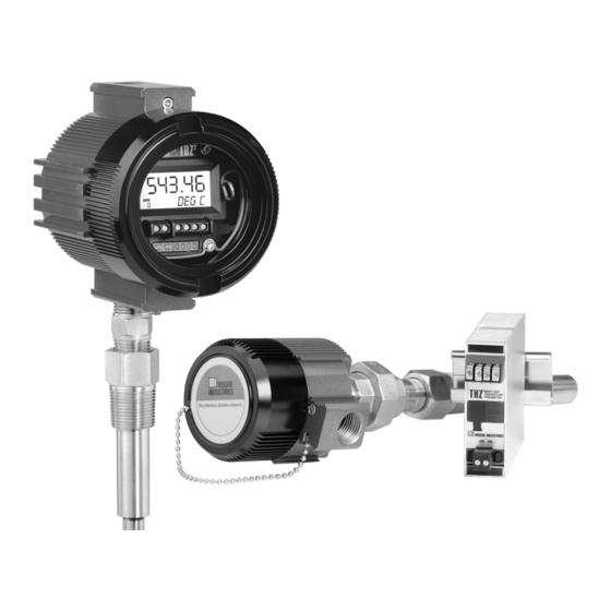
- Page 1 & TPRG ay 201 Programmable Smart HART 235-797-01 Temperature Transmitter and Display...
-
Page 2: Table Of Contents
Table of Contents Introduction ............................. About this Manual ......................4 The THZ and TDZ ..................4 Model and Serial Numbers .................... 4 Specifications ....................5 Input Type and Accuracy Table ..................6 Stability, Ambient Temperature Effects and Normal Mode Rejection Ratio Tables ................7 Dimensions ........................ - Page 3 HART Status Information ................29 Installation ..................... 32 2 ............................Mounting the THZ and TDZ Making the Electrical Connections ................. 32 Recommended Ground Wiring Practices ............... 32 CE Conformity ........................ 33 Installation in Hazardous Locations ............34 Operation ....................... 35 HART Protocol ........................
-
Page 4: Introduction
TDZ allow for configuration through two methods. You may use your PC’s RS-232 serial port or USB port and Moore Industries’ PC About this Manual Configuration Software (once installed onto your PC). Pay particular attention wherever you see a “Note”, All configuration parameters are available through the “Caution”... -
Page 5: Specifications
& Programmable Smart HART Temperature Transmitter and Display Specifications HART Performance Load Effect: Negligible Display Address Range: 0-15 Decimal Points: Specifications (1-15 are for multidrop loops) (Continued) within specified power limits (TDZ only, Can be user-set to enable continued) Transmission Speed: Load Capability: automatic adjustment of (500 ohms@24V) -
Page 6: Input Type And Accuracy Table
& Programmable Smart HART Temperature Transmitter and Display Table 1. THZ and TDZ Input and Accuracy Table Sensor-to- α Conformance Minimum Input Maximum Input Type Ohms Transmitter Range Span Accuracy Range Matching Up to ±0.014°C (±0.025°F) system accuracy*. *High-accuracy -240 to 960°C -200 to 850°C 0.003850 measurements are... -
Page 7: Stability, Ambient Temperature Effects And Normal Mode Rejection Ratio Tables
& Programmable Smart HART Temperature Transmitter and Display Table 2. Long-Term Stability Table Table 4. Normal Mode Rejection Ratio Table Max. p-p Voltage Injection for Stability (% Sensor Type Input to Output Input to HART 70dB at 50/60Hz of maximum T/C: J, K, N, C, E 150mV span) - Page 8 & Programmable Smart HART Temperature Transmitter and Display Figure 2. TDZ Hockey-Puck (HP Housing) Dimensions 76mm 66mm (3.0 in) (2.5 in) 61mm (2.4 in) 18mm 83mm (0.70 in) 62mm (3.2 in) (2.4 in) 43mm (1.7 in) 64mm (2.5 in) SIDE VIEW FRONT VIEW Figure 3.
- Page 9 & Programmable Smart HART Temperature Transmitter and Display Figure 4. BH Housing Dimensions (For use with the TDZ SIDE VIEW 102mm (4.0 in ) 119mm (4.6 in ) 76mm 1/2 NPT 57mm (2.9 in ) (2.2 in ) 22mm (0.8 in ) TOP VIEW 64mm (2.5 in )
- Page 10 & Programmable Smart HART Temperature Transmitter and Display Figure 5. LH Housing Dimensions (For use with the THZ HPP) BOTTOM 87mm 51mm Safety Lock (3.4 in) (2.0 in) (LH2 only) SIDE Metal Tag Conduit 61mm Entry Port (2.4 in) 92mm (3.62 in) 30mm 10-32...
-
Page 11: Configuring The Thz
Configuring the THZ Installing the Configuration Software Refer to Table 5 for the equipment needed. Insert the Moore Industries Interface Solution One of the benefits of these transmitters is that there PC Configuration Software CD into the CD are no internal or external controls to adjust or settings drive of the PC. -
Page 12: Connecting The Thz 2 Or Tdz 2 To The Pc
Connect your instrument to the PC via the RS-232 a loop test, receive (via download) a configuration file serial port using Moore Industries Interface cable or and save the configuration file from the transmitter’s USB cables listed in Table 5. - Page 13 & Programmable Smart HART Temperature Transmitter and Display Figure 7. THZ (HPP) and TDZ (HP) Hook-Up Diagrams Current Meter THZ (HPP) Hook-Up – Load=250 ohms 12-24Vdc Power Supply THE HART Communicator or the PC can be connected –PS at any point on the output side of the loop.
- Page 14 & Programmable Smart HART Temperature Transmitter and Display Figure 8. THZ DIN Hook-Up Diagram Current Meter +PS –PS – Load = 250 ohms 12-24Vdc Power Supply To USB HART Modem (COM) connects to Port of PC serial (COM) port of PC THE HART Communicator or the PC can be connected at any point on the output...
-
Page 15: Pc Configuration Software Summary
Set. To view the Long Tag, click Read. 1. Menu Bar/Tool Bar– Dropdown menus and 5. THZ2/TDZ2 Device Info– This “read-only” display corresponding icons allow you to perform various functions throughout the PC Configuration Program. indicates instrument configuration and device Refer to the Menu and Tool Bar Legend for a complete identification. -
Page 16: Menu And Tool Bar Legend
& Programmable Smart HART Temperature Transmitter and Display Configuration Screens Figure 9-B. THZ /TDZ PC Configuration Software Main Screen Note: Unless otherwise noted, ensure that the PC Configuration Program is idle before making any selections or configuration changes to the program. Also, when attempting to download or upload, monitoring must be stopped. - Page 17 To utilize Broken Wire Detection, check the Enabled correctly. box. If a failure is detected, a message will appear in the THZ2/TDZ2 Status box. You may trim any point between 0% and 100% along the scale. Note that one-point trimming applies an Running Average Filter Settings–...
- Page 18 & Programmable Smart HART Temperature Transmitter and Display Display (TDZ Only) Scaling Figure 11. Display Tab Figure 12. Scaling Tab Note: Using the Scaling feature will disable the Custom Curve capability. Since both are scaling features used to manipulate the appearance of your process variable, only one of these functions may be used at Display Source–...
- Page 19 & Programmable Smart HART Temperature Transmitter and Display Custom Curve To create a custom curve: Click the Enabled box. Figure 13. Custom Curve Tab Select the number of points for your curve (128 points maximum) and enter it into the No Of Points text box.
-
Page 20: Analog Output
& Programmable Smart HART Temperature Transmitter and Display Analog Output Hold Last– This will maintain the last value present before the failure. Figure 14. Analog Output Tab Note: Once you have configured all parameters, download to the unit by selecting Download in the Transfer dropdown menu located in the Menu Bar. -
Page 21: Searching For A Connected Unit
Note: HART Communication Foundation While performing Analog Output Trimming functions, 9390 Research Blvd., Suite I-350 you may notice a message in the THZ2/TDZ2 Status Austin, TX 78759-6540 display reading **OUTPUT FIXED**” Clicking the Unfix button will clear this message. Phone: (512) 794-0369 Fax: (512) 794-3904 www.hartcomm.org... - Page 22 & Programmable Smart HART Temperature Transmitter and Display Figure 15. THZ and TDZ HART Communicator Configuration Menu Summary Online Menu 1 Model 2 Device Setup Sensor Type 3 PV Configure Sensor 4 AO 1 RTD2W 4 LRV 1 Sensor Type 1 PT3850 100 6 URV 2 RTD3W...
-
Page 23: The Hart Communicator Menu With A Device Description
& Programmable Smart HART Temperature Transmitter and Display The HART Communicator Menu With a B. Configure Options You may configure the THZ and TDZ options listed Device Description below from the this menu. To program your THZ or TDZ , if your communicator is equipped with the Device Description for 1 EGU Selection–... - Page 24 & Programmable Smart HART Temperature Transmitter and Display Smart Range Selection– Select whether you choose 5 Custom Curve LRV– Enter your Custom Curve to view the process variable, use a custom curve table lower range value (LRV) for the lower end output value or scale the input.
- Page 25 & Programmable Smart HART Temperature Transmitter and Display Note: 3 Output Trim– Output trimming increases the For Fisher-Rosemount HART Communicator, Model accuracy of your instrument by calibrating its analog output to the device that is receiving the output. 275, you must enable the Burst Mode and send the This ensures that the instrument is being correctly configuration to the unit before selecting the Burst Option.
- Page 26 & Programmable Smart HART Temperature Transmitter and Display 4 Label Displayed– Select your custom label. Enter all capitalized characters or an accepted numeric value. 5. Diagnostic & Service Menu– Allows you to perform diagnostic functions (device test and loop tests) and sensor trimming. 1 Test device–...
- Page 27 & Programmable Smart HART Temperature Transmitter and Display Figure 16. Generic HART Communicator Menu Overview Process Variable Online Generic Device Setup 1 Snsr 1 Device Setup 1 Process Variables 2 AI % 2 PV 3 A01 Display 3 PV AO Diag/Service 4 PV LRV 2 Diag/Service...
-
Page 28: The Hart Communicator Menu Without A Device Description
& Programmable Smart HART Temperature Transmitter and Display The HART Communicator 3. Analog Output– The Analog Output menu displays the analog output, changes the loop current to a fixed Menu Without a Device value so that it can be checked against the value be- ing received and displayed by your receiving device, Description and enters and trims the sensor. -
Page 29: Hart Status Information
& Programmable Smart HART Temperature Transmitter and Display HART Status Information that is returned in every response message. However, they do not detail the transmitter-specific Additional Each time the THZ and TDZ generate a response, Status Information that is returned in the data portion frame status information is included in the reply mes- of the response to HART Command 48. - Page 30 & Programmable Smart HART Temperature Transmitter and Display Table 8. Device Status Bytes Table Type Description Primary Variable Out of Limits. The process applied to the sensor for the Primary Variable is beyond Error the operating limits of the device. Non-Primary Variable Out of Limits.
- Page 31 & Programmable Smart HART Temperature Transmitter and Display HART Command 48 The Additional Status Information section in the View dropdown menu returns five additional HARTstatus information bytes in response to HART Command 48– Read Additional HART Status Information. The five data bytes are described in Table 10. Table 10.
-
Page 32: Installation
Installation consists of physically mounting the unit and completing the electrical connections. Moore Industries recommends the following ground wiring practices: • Any Moore Industries product in a metal case or Mounting the THZ or TDZ housing should be grounded. The THZ HPP fits inside a 30-35mm connection head •... -
Page 33: Ce Conformity
CE Conformity Installation of any Moore Industries’ products that carry the CE marking must adhere to the guidelines in the Recommended Ground Wiring Practices section in order to meet the EN 61326 requirements set forth in the applicable EMC directive. -
Page 34: Installation In Hazardous Locations
& Programmable Smart HART Temperature Transmitter and Display Installation in Hazardous Safety Concerns For your safety, read the following information carefully Locations’ before proceeding with installation. This page contains information for the THZ and TDZ instruments when used within an intrinsically-safe WARNING: EXPLOSION HAZARD –... -
Page 35: Operation
Maintenance eration. For more information on the HART protocol, Moore Industries suggests a quick check for termi- contact the HART Foundation at: nal tightness and general unit condition every 6-8 months. Always adhere to any site requirements for HART Communication Foundation programmed maintenance. - Page 39 4. Ship the equipment to the Moore Industries location nearest you. The returned equipment will be inspected and tested at the factory. A Moore Industries rep- resentative will contact the person designated on your documentation if more information is needed.
Need help?
Do you have a question about the TDZ2 and is the answer not in the manual?
Questions and answers