Advertisement
Quick Links
I N S T A L L A T I O N I N S T R U C T I O N S
MCB1U
(Shown installed to
CPA Series extension column
as example only)
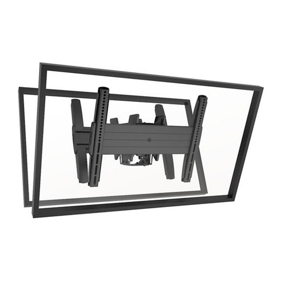
Back-to-Back Flat Panel Ceiling Mounts
LCB1U
(Shown installed to
1-1/2" NPT column as example only)
Spanish Product Description
German Product Description
Portuguese Product Description
Italian Product Description
Dutch Product Description
French Product Description
MCB1U / LCB1U
Advertisement

Related Manuals for CHIEF LCB1U


Summary of Contents for CHIEF LCB1U
- Page 1 (Shown installed to 1-1/2" NPT column as example only) CPA Series extension column as example only) Back-to-Back Flat Panel Ceiling Mounts Spanish Product Description German Product Description Portuguese Product Description Italian Product Description Dutch Product Description French Product Description MCB1U / LCB1U...
-
Page 2: Important Safety Instructions
(not included); OR a UL Listed Chief CPA Series extension column (not included). Chief® is a registered trademark of Milestone AV Technologies. All rights reserved. NOTE: The MCB1U/LCB1U mounts are intended to be used with the UL Listed CPA Ceiling Plates (not included): CPA330, CPA365, CPA395. - Page 3 Installation Instructions MCB1U / LCB1U DIMENSIONS MCB1U 20.82 DIMENSIONS: INCHES 528.9 [MILLIMETERS] LCB1U 24.38 619.1 MAX MOUNTING PATTERN WIDTH 26.83 681.5 DIMENSIONS: INCHES [MILLIMETERS]...
- Page 4 MCB1U / LCB1U Installation Instructions LEGEND Tighten Fastener Adjust Apretar elemento de fijación Ajustar Befestigungsteil festziehen Einstellen Apertar fixador Ajustar Serrare il fissaggio Regolare Bevestiging vastdraaien Afstellen Serrez les fixations Ajuster Loosen Fastener Remove Aflojar elemento de fijación Quitar Befestigungsteil lösen...
-
Page 5: Tools Required For Installation
Installation Instructions MCB1U / LCB1U TOOLS REQUIRED FOR INSTALLATION 3/32" (included) 1/8" (included) 5/32" (included) (included) 1/2" or 13mm PARTS [Interface Bracket Hardware Kit] (2 bags total - quantities listed per bag) D (6) C (6) A (8) B (6) - Page 6 NPT or NPSM following ANSI/ASME B1.20.1 (Schedule 40, 0.154" minimum thickness steel or aluminum-ASTM B221) threaded extension column (not included); or a UL Listed Chief CPA Series extension column (not included) - - has been properly installed and is in place. NOTE:...
- Page 7 Installation Instructions MCB1U / LCB1U Install two 5/16" x 1" self-tapping screws (U) through two 5/16" flat washers (V), bottom stop collar (BB), and into installed column. (L or M) Install and tighten 5/16" x 3/4" set screw (X) into bottom stop collar (BB).
- Page 8 MCB1U / LCB1U Installation Instructions Attaching Displays to Ceiling Mount Ensure that the latch mechanisms on interface brackets (FF) are already lowered. (See Figure 5) While supporting both sides of display, lower display onto ceiling mount, hooking top of interface brackets onto front of ceiling mount.
- Page 9 Installation Instructions MCB1U / LCB1U Tilt The ceiling mounts allow -5° to 20° tilt. The ceiling mount can (Z) x 2 be locked at 0°, 5°, 10° and 15° tilt. Loosen two tilt friction screws (located each side). (See Figure 10) (AA) x 2 Adjust tilt as required.
- Page 10 MCB1U / LCB1U Installation Instructions Installing Covers Install two interface bracket covers (GG) over the top and bottom of each interface bracket. (See Figure 13) (W) x 4 NOTE: Be sure to line up tabs inside the bracket covers with holes on sides of interface brackets.
- Page 11 Installation Instructions MCB1U / LCB1U...
- Page 12 Europe A Franklinstraat 14, 6003 DK Weert, Netherlands P +31 (0) 495 580 852 F +31 (0) 495 580 845 Chief Manufacturing, a products division Asia Pacific A Office No. 1 on 12/F, Shatin Galleria of Milestone AV Technologies 18-24 Shan Mei Street...
Need help?
Do you have a question about the LCB1U and is the answer not in the manual?
Questions and answers