
Related Manuals for Simrad 38-7 - INSTALLATION REV D


Summary of Contents for Simrad 38-7 - INSTALLATION REV D
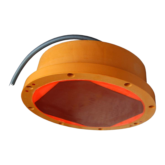
- Page 1 Installation manual Simrad 38-7 38 kHz single beam transducer www.simrad.com T E C H N O L O G Y F O R S U S T A I N A B L E F I S H E R I E S...
- Page 3 Simrad 38-7 Installation manual This document provides a general description of how to install the Simrad 38-7 Single beam transducer. The information must be regarded as general guidelines and recommendations only. The installation shipyard must design and manufacture installation hardware to fit the 38-7 transducer on each individual vessel.
- Page 4 If you require maintenance or repair, contact your local dealer. You can also contact us using the following address: contact@simrad.com. If you need information about our other products, visit our web site. On the web site you will also find a list of our dealers and distributors.
-
Page 5: Table Of Contents
Installation manual Table of contents ABOUT THIS MANUAL ............5 SIMRAD 38-7 ..............6 WHERE TO MOUNT THE TRANSDUCER ....... 7 HOW TO INSTALL THE TRANSDUCER ......11 Transducer installation in blister ................11 Use the mounting ring ................. 11 Smooth surface is important ................ - Page 6 Simrad 38-7 Introduction to Emuge self-locking threads........... 25 Drawing standard..................26 Taps and gauges..................26 Self-lock taps provided by Simrad ............... 27 Supplier and manufacturer................27 TRANSDUCER CABLE SPLICING........28 DRAWING FILE ............... 29 Echo sounder connections ..................29 Splicing the transducer cable ............... 29 General Purpose Transceiver (GPT) wiring...........
-
Page 7: About This Manual
Whenever required, the installation shipyard must also have the installation approved by the applicable maritime authorities. Additional information For additional detailed information about the transducer to be installed, refer to the documentation provided with the transducer. Drawings and descriptions can also be obtained from http://www.simrad.com. 130003/D... -
Page 8: Simrad 38-7
The drawings specific for the 38-7 transducer are located in the Drawing file on page 29. Technical specifications Refer to the Simrad 38-7 data sheet. You can read and/or download the data sheet on http://www.simrad.com. Additional parts provided for installation The following items can be supplied by Simrad to facilitate installation. -
Page 9: Where To Mount The Transducer
Where to mount the transducer WHERE TO MOUNT THE TRANSDUCER A single answer to the question where to locate the transducer cannot be given. It depends very much on the vessel’s construction, how the hull is shaped and how the water runs along the hull. - Page 10 Simrad 38-7 Mount the transducer at the forward part of the hull to minimise the effects from the boundary water layer When the vessel forces its way through the sea, the friction between the hull and the water creates a boundary layer. The thickness of the boundary layer depends upon vessel speed and the roughness of the hull.
- Page 11 Where to mount the transducer Mount the transducer far away from the propellers The propulsion propeller is the dominant noise source on most fishing vessels, research vessels, merchant vessels and pleasure crafts. The noise is transmitted through the sea water. For this reason, the transducer should be placed far away from the propeller, which means on the fore part of the hull.
- Page 12 Simrad 38-7 Summary and general recommendations Some of the above guide lines are conflicting, and each case has to be treated individually in order to find the best compromise. Generally the propeller noise is the dominant factor, and a recommended transducer location is in the fore part of the hull, with maximum distance from the bow equal to one third of the total length of the hull at the water line.
-
Page 13: How To Install The Transducer
Large circular transducers are designed to be mounted using a mounting ring. A suitable mounting can be provided by Simrad, drawings are also available for local production. The mounting ring is welded to the hole prepared for the transducer. Bolts through the transducer body into the mounting ring will secure the transducer in place. -
Page 14: Example: Large Circular Transducer
Simrad 38-7 Example: Large circular transducer The illustration below shows a typical transducer blister designed for a large transducer. Note that due to the physical size of the transducer, a U-shaped support bar (E) is used to support the transducer. The purpose of this support is to prevent the transducer from being pushed up into the blister in heavy seas. -
Page 15: Toe-In
How to install the transducer The interior of the blister must be filled with sea water. Use drainage holes in the bottom and an air outlet on the top. The water pressure behind the transducer will then compensate for the outside pressure during vessel movements in rough sea. We recommend that large diameter transducers are fitted with a horizontal U-shaped support bar. -
Page 16: Transducer Installation In Box Keel
Large circular transducers are designed to be mounted using a mounting ring. A suitable mounting can be provided by Simrad, drawings are also available for local production. The mounting ring is welded to the hole prepared for the transducer. Bolts through the transducer body into the mounting ring will secure the transducer in place. -
Page 17: Use A Horizontal Support Bar On Large Transducers
How to install the transducer mount it, the hull plating and the putty around the transducer is as even and smooth as possible. Obstructions on these surfaces will create problems with turbulent flow. Use a horizontal support bar on large transducers Due to its physical size, the 38-7 transducer must be fitted with a horizontal support bar. -
Page 18: Use The Mounting Ring
Large circular transducers are designed to be mounted using a mounting ring. A suitable mounting can be provided by Simrad, drawings are also available for local production. The mounting ring is welded to the hole prepared for the transducer. Bolts through the transducer body into the mounting ring will secure the transducer in place. -
Page 19: Example: Flush Mounting In A Steel Tank
Transducer with acoustic window Vessels operating in arctic waters need special attention on transducer installation. Floating blocks of ice may damage even a flush mounted transducer face. For this situation Simrad offers arctic tanks in different sizes. Use the mounting ring Large circular transducers are designed to be mounted using a mounting ring. -
Page 20: Example: Acoustic Window
The loss varies with the distance between transducer face and the hull. The best result is obtained when the distance is half a wavelength. Consult Simrad for advice. In addition to the loss, the beam pattern is degraded, because a larger area of the hull is set into vibrations. -
Page 21: Use The Mounting Ring
Large circular transducers are designed to be mounted using a mounting ring. A suitable mounting can be provided by Simrad, drawings are also available for local production. The mounting ring is welded to the hole prepared for the transducer. Bolts through the transducer body into the mounting ring will secure the transducer in place. -
Page 22: Transducer Mounted On A Drop Keel
Simrad 38-7 Transducer mounted on a drop keel The use of a drop keel with the purpose of stabilising the vessel is well known. A drop keel is also a superior platform for echo sounder transducers. Such instrument keels have been built, mainly on research vessels, often protruding as far as three meters below the hull. -
Page 23: Retractable Transducer
How to install the transducer Retractable transducer Hull units allowing the transducer to be lowered and hoisted are commonly used for horizontal looking sonars. When not in use, the transducer is retracted into a trunk. The retractable hull unit is more expensive than a blister, but on vessels with a hull where it is difficult or impossible to install a blister, it may still be worth while. -
Page 24: Steel Conduit
Simrad 38-7 STEEL CONDUIT Why use steel conduits? It is strongly recommended to lay a steel conduit from the transducer’s cable gland to the echo sounder transceiver, and to pull the transducer cable through this conduit. There are several reasons for this. -
Page 25: Transducer Handling And Maintenance
An anti-fouling paint may be applied to the transducer face. Because some paint types may be aggressive to the polyurethane in the transducer face, please consult Simrad’s list of approved paints. See Approved anti-fouling paints on page 24. Cleaning the transducer face... -
Page 26: Approved Anti-Fouling Paints
Simrad 38-7 Approved anti-fouling paints This is Simrad’s list of approved antifouling paints on polyurethane transducer housing. Jotun Head office address: P.O.Box 2021, N-3248 Sandefjord, Norway Website: www.jotun.com. Racing Non-stop Safeguard Universal primer (125 micron) with Antifouling SeaQuantum Ultra (125 micron) -
Page 27: Introduction To Emuge Self-Locking Threads
Transducer handling and maintenance Introduction to Emuge self-locking threads is a tap design with an integrated locking feature. Emuge self-lock Standard metric bolts are used. The internal thread provides a self-locking connection, which can be used repeatedly. It is not necessary to involve a secondary locking device (e.g. -
Page 28: Drawing Standard
Simrad 38-7 • Economically efficient locking system, no additional components are necessary • Undiminished holding power even under dynamic stress • Repeated loosening and re-tightening without loss of function • Internal threads can be produced with taps, cold Emuge forming taps or thread mills •... -
Page 29: Self-Lock Taps Provided By Simrad
Note that the gauge must be used Emuge self-lock in the correct direction. Self-lock taps provided by Simrad The following self-lock taps are on stock at Simrad, and can be ordered from us. Threads Drill diameter for Part.no threads ø5.2... -
Page 30: Transducer Cable Splicing
If you need to cut or lengthen the transducer cable, you must splice it correctly. The cable between the junction box and the transceiver must then be supplied by Simrad, and this must be the same type as used on the transducer(s). To splice the cable, use a metal junction box with EMC cable glands and a terminal block. -
Page 31: Drawing File
Drawing file DRAWING FILE This chapter contains relevant drawings related to the electrical and physical installation of the Simrad 38-7 Single beam transducer. Note The mechanical drawings are for information and guidance only. They are not in scale, and may differ slightly from the original drawings. -
Page 32: General Purpose Transceiver (Gpt) Wiring
Simrad 38-7 General Purpose Transceiver (GPT) wiring Observe the drawings below to connect the Simrad 38-7 Single beam transducer to the General Purpose Transceiver (GPT). For more information about these connections, refer to the applicable echo sounder installation manual. 130003/D... -
Page 33: General Purpose Transceiver (Gpt) Transducer Plug Assembly
Drawing file General Purpose Transceiver (GPT) transducer plug assembly 130003/D... -
Page 34: Outline Dimensions And Installation Drawings
Loctite 270 on each bolt, and tighten the bolts several times. Use maximum torque 32 Nm. In addition to the drawings available in this chapter, additional drawings are provided on our web site. See www.simrad.com. Topics • Outline dimensions [074647] on page 33 •... -
Page 35: Outline Dimensions [074647]
Drawing file Outline dimensions [074647] 130003/D... -
Page 36: Mounting Ring [074076]
Simrad 38-7 Mounting ring [074076] 130003/D... - Page 37 Drawing file 130003/D...
-
Page 38: Recommended Arrangement [074544]
Simrad 38-7 Recommended arrangement [074544] 130003/D... - Page 39 Drawing file 130003/D...
-
Page 40: Mounting Procedure [088759]
Simrad 38-7 Mounting procedure [088759] 130003/D... -
Page 41: Support Bar [206574]
Drawing file Support bar [206574] 130003/D... - Page 42 Simrad 38-7 130003/D...
- Page 43 Index Index Clamping ring, 38 angle, 9 GPT Transducer plug, 31 Inside the hull About, 5 mounting arrangement, 36 example, 19 information in this Mounting ring, 34 installation, 18 manual, 5 outline dimensions, 33 Installation Acoustic window, 23 Support bar, 39 drawings, 6, 29 example, 18 Drawing file, 29...
- Page 44 5 Wiring General Purpose Transceiver, 30 Retractable installation, 21 Self-locking taps, 25 Shielding steel conduit, 22 Simrad website, 5 Smooth surface, 11, 14, 16–17, 19 Splicing transducer cable, 28–29 Steel conduit diameter, 22 qualities, 22 shielding, 22 why, 22...
- Page 45 Index 130003/D...
- Page 48 Simrad document number: 130003 / Version D ISBN-13: 978-82-8066-111-1 © 2009 Kongsberg Maritime AS...
Need help?
Do you have a question about the 38-7 - INSTALLATION REV D and is the answer not in the manual?
Questions and answers