Simrad 38-200 COMBI W - INSTALLATION REV D Installation Manual
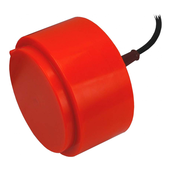
Dual frequency echo sounder transducer
Hide thumbs
Also See for 38-200 COMBI W - INSTALLATION REV D:
- Installation manual (33 pages) ,
- Datasheet (2 pages) ,
- Datasheet (2 pages)

Related Manuals for Simrad 38-200 COMBI W - INSTALLATION REV D


Summary of Contents for Simrad 38-200 COMBI W - INSTALLATION REV D
- Page 1 Installation manual Simrad 38/200 Combi W Dual frequency echo sounder transducer www.simrad.com T E C H N O L O G Y F O R S U S T A I N A B L E F I S H E R I E S...
- Page 3 Simrad 38/200 Combi W Installation manual This document provides a general description of how to install the Simrad 38/200 Combi W Dual frequency transducer. The information must be regarded as general guidelines and recommendations only. The installation shipyard must design and manufacture installation hardware to fit the 38/200 Combi W transducer on each individual vessel.
- Page 4 Document history Document number: 164986 / ISBN-13: 978-82-8066-035-0 Rev.A 08.11.04 First version. Rev.B 20.05.05 Added information about cable glands. Corrected error on the outline dimension drawing on page 29. Rev.C 06.06.05 The correct outer diameter is 180 mm. Rev.D 06.10.09 Additional information added.
-
Page 5: Table Of Contents
Installation manual Table of contents ABOUT THIS MANUAL ............5 SIMRAD 38/200 COMBI W ..........6 WHERE TO MOUNT THE TRANSDUCER ....... 7 HOW TO INSTALL THE TRANSDUCER ......11 Transducer installation in blister ................11 Use mounting and clamping rings whenever provided ........11 Smooth surface is important ................ - Page 6 Using self-locking taps ...................29 Introduction to Emuge self-locking threads........... 30 Drawing standard..................31 Taps and gauges..................31 Self-lock taps provided by Simrad ............... 32 Supplier and manufacturer................32 DRAWING FILE ............... 33 Echo sounder connections ..................33 Splicing the transducer cable ............... 33 General Purpose Transceiver (GPT) wiring...........
-
Page 7: About This Manual
Whenever required, the installation shipyard must also have the installation approved by the applicable maritime authorities. Additional information For additional detailed information about the transducer to be installed, refer to the documentation provided with the transducer. Drawings and descriptions can also be obtained from http://www.simrad.com. 164986/D... -
Page 8: Simrad 38/200 Combi W
Combi W transducer are located in the Drawing file on page 33. Technical specifications Refer to the Simrad 38/200 Combi W data sheet. You can read and/or download the data sheet on http://www.simrad.com. Additional parts provided for installation The following items can be supplied by Simrad to facilitate installation. -
Page 9: Where To Mount The Transducer
Where to mount the transducer WHERE TO MOUNT THE TRANSDUCER A single answer to the question where to locate the transducer cannot be given. It depends very much on the vessel’s construction, how the hull is shaped and how the water runs along the hull. - Page 10 Simrad 38/200 Combi W Mount the transducer at the forward part of the hull to minimise the effects from the boundary water layer When the vessel forces its way through the sea, the friction between the hull and the water creates a boundary layer. The thickness of the boundary layer depends upon vessel speed and the roughness of the hull.
- Page 11 Where to mount the transducer Mount the transducer far away from the propellers The propulsion propeller is the dominant noise source on most fishing vessels, research vessels, merchant vessels and pleasure crafts. The noise is transmitted through the sea water. For this reason, the transducer should be placed far away from the propeller, which means on the fore part of the hull.
- Page 12 Simrad 38/200 Combi W Summary and general recommendations Some of the above guide lines are conflicting, and each case has to be treated individually in order to find the best compromise. Generally the propeller noise is the dominant factor, and a...
-
Page 13: How To Install The Transducer
How to install the transducer HOW TO INSTALL THE TRANSDUCER There are many different ways to mount the transducer. These are the recommended methods to mount a circular transducer. Transducer installation in blister With a transducer with circular housing, one recommended installation method is by using a blister. -
Page 14: Example: Small Circular Transducer
Simrad 38/200 Combi W Example: Small circular transducer The illustration below shows a typical transducer blister designed for a small transducer. The same blister design principles as for a large transducer apply. Figure 4 Small circular transducer Streamlined blister Mounting ring... -
Page 15: Toe-In
How to install the transducer The interior of the blister must be filled with sea water. Use drainage holes in the bottom and an air outlet on the top. The water pressure behind the transducer will then compensate for the outside pressure during vessel movements in rough sea. We recommend that large diameter transducers are fitted with a horizontal U-shaped support bar. -
Page 16: Transducer Installation In Box Keel
Simrad 38/200 Combi W Observe the horizontal and vertical distances (C and D) between the keel and the transducer blister. On a medium sized vessel, the horizontal distance (C) should be approximately 1 meter. The vertical distance (D) must in general be as small as possible. This is important to prevent the keel from shadowing the transducer beam in shallow waters. -
Page 17: Smooth Surface Is Important
How to install the transducer Smooth surface is important Mounting screws or bolts must not be extruding from the transducer or the area immediately around it. Make sure that the surface of the transducer face, the installation hardware used to mount it, the hull plating and the putty around the transducer is as even and smooth as possible. -
Page 18: Smooth Surface Is Important
Simrad 38/200 Combi W mounting ring will secure the transducer between them. Note that several transducers use direction guides to allow correct mounting. Smooth surface is important Mounting screws or bolts must not be extruding from the transducer or the area immediately around it. Make sure that the... -
Page 19: Transducer With Acoustic Window
Transducer with acoustic window Vessels operating in arctic waters need special attention on transducer installation. Floating blocks of ice may damage even a flush mounted transducer face. For this situation Simrad offers arctic tanks in different sizes. Use mounting and clamping rings... -
Page 20: Example: Acoustic Window
The loss varies with the distance between transducer face and the hull. The best result is obtained when the distance is half a wavelength. Consult Simrad for advice. In addition to the loss, the beam pattern is degraded, because a larger area of the hull is set into vibrations. -
Page 21: Use Mounting And Clamping Rings Whenever Provided
How to install the transducer Use mounting and clamping rings whenever provided Circular transducers may be provided with mounting and clamping rings, or with drawings to allow for local production of these. The mounting ring is welded to the hole prepared for the transducer, while the clamping ring fits around the edge of the transducer body. -
Page 22: Transducer Mounted On A Drop Keel
Simrad 38/200 Combi W Transducer mounted on a drop keel The use of a drop keel with the purpose of stabilising the vessel is well known. A drop keel is also a superior platform for echo sounder transducers. Such instrument keels have been built, mainly on research vessels, often protruding as far as three meters below the hull. -
Page 23: Retractable Transducer
How to install the transducer Retractable transducer Hull units allowing the transducer to be lowered and hoisted are commonly used for horizontal looking sonars. When not in use, the transducer is retracted into a trunk. The retractable hull unit is more expensive than a blister, but on vessels with a hull where it is difficult or impossible to install a blister, it may still be worth while. -
Page 24: Transducer Cable Glands And Splicing
Note Simrad strongly recommends that a length of conduit is fitted around transducer cable glands made of steel or bronze and extended over the water-line inside the vessel. This precaution reduces the danger of flooding in the event of gland failure and transducers installed in this manner are also easier to replace. -
Page 25: Cable Gland For Steel Hulls
The cable gland kit includes all of the necessary parts needed to install the unit except screws. Simrad recommends that a one inch steel conduit (that the transducer cable will be run through) with an inside threaded diameter of three-quarter inches is welded to the gland’s stuffing tube. -
Page 26: Cable Gland For Wooden And Grp Hulls
The cable gland kit includes all of the necessary parts needed to install the unit except screws. Simrad recommends that a one inch steel conduit (that the transducer cable will be run through) with an inside threaded diameter of three-quarter inches is attached to the gland’s packing nipple. -
Page 27: Cable Glands For Small Hulls
Transducer cable glands and splicing Cable glands for small hulls This cable glands made of plastic is designed for those smaller vessels that do not need to be classified. Packing nut (bronze). Make sure that you do not to damage the transducer cable by tightening the packing nut too hard! Rubber gasket Plastic disk... -
Page 28: Transducer Cable Splicing
If you need to cut or lengthen the transducer cable, you must splice it correctly. The cable between the junction box and the transceiver must then be supplied by Simrad, and this must be the same type as used on the transducer(s). To splice the cable, use a metal junction box with EMC cable glands and a terminal block. -
Page 29: Steel Conduit
Steel conduit STEEL CONDUIT Why use steel conduits? It is strongly recommended to lay a steel conduit from the transducer’s cable gland to the echo sounder transceiver, and to pull the transducer cable through this conduit. There are several reasons for this. •... -
Page 30: Transducer Handling And Maintenance
An anti-fouling paint may be applied to the transducer face. Because some paint types may be aggressive to the polyurethane in the transducer face, please consult Simrad’s list of approved paints. See Approved anti-fouling paints on page 29. Cleaning the transducer face... -
Page 31: Approved Anti-Fouling Paints
Transducer handling and maintenance Approved anti-fouling paints This is Simrad’s list of approved antifouling paints on polyurethane transducer housing. Jotun Head office address: P.O.Box 2021, N-3248 Sandefjord, Norway Website: www.jotun.com. Racing Non-stop Safeguard Universal primer (125 micron) with Antifouling SeaQuantum Ultra (125 micron) -
Page 32: Introduction To Emuge Self-Locking Threads
Simrad 38/200 Combi W Introduction to Emuge self-locking threads is a tap design with an integrated locking feature. Emuge self-lock Standard metric bolts are used. The internal thread provides a self-locking connection, which can be used repeatedly. It is not necessary to involve a secondary locking device (e.g. -
Page 33: Drawing Standard
Note: The self-lock threads marked with SL* must be made in accordance with procedure 842–202125. Drill diameters for threads differ from standard. Self-lock taps can be supplied by Simrad. Taps and gauges The pretension locking thread self–lock (taps) from manufacturer must be used. -
Page 34: Self-Lock Taps Provided By Simrad
Note that the gauge must be used Emuge self-lock in the correct direction. Self-lock taps provided by Simrad The following self-lock taps are on stock at Simrad, and can be ordered from us. Threads Drill diameter for Part.no threads ø5.2... -
Page 35: Drawing File
Drawing file DRAWING FILE This chapter contains relevant drawings related to the electrical and physical installation of the Simrad 38/200 Combi W Dual frequency transducer. Note The mechanical drawings are for information and guidance only. They are not in scale, and may differ slightly from the original drawings. -
Page 36: General Purpose Transceiver (Gpt) Wiring
Simrad 38/200 Combi W General Purpose Transceiver (GPT) wiring Observe the drawing below to connect the Simrad 38/200 Combi W Dual frequency transducer to the General Purpose Transceiver (GPT). For more information about these connections, refer to the applicable echo sounder installation manual. -
Page 37: General Purpose Transceiver (Gpt) Transducer Plug Assembly
Drawing file General Purpose Transceiver (GPT) transducer plug assembly 164986/D... -
Page 38: Outline Dimensions And Installation Drawings
Simrad 38/200 Combi W Outline dimensions and installation drawings Note Observe the 32 Nm torque when the transducer is mounted using the mounting and clamping rings. Observe the 17 Nm maximum torque when the transducer is mounted using the threaded inserts on the transducer body . -
Page 39: Outline Dimensions [208889]
Drawing file Outline dimensions [208889] 164986/D... -
Page 40: Mounting Ring [208846]
Simrad 38/200 Combi W Mounting ring [208846] 164986/D... - Page 41 Drawing file 164986/D...
-
Page 42: Clamping Ring [204677]
Simrad 38/200 Combi W Clamping ring [204677] 164986/D... - Page 43 Drawing file 164986/D...
-
Page 44: Recommended Arrangement [204678]
Simrad 38/200 Combi W Recommended arrangement [204678] 164986/D... - Page 45 Drawing file 164986/D...
- Page 46 Simrad 38/200 Combi W Index Dimensions drawing, 37 About, 5 Inclination Drawing information in this angle, 9 arrangement, 42 manual, 5 Inside the hull Clamping ring, 40 Acoustic window, 28 example, 19 GPT Transducer plug, 35 example, 18 installation, 18...
- Page 47 Transceiver, 34 Wooden hull cable gland, 24 Retractable installation, 21 Self-locking taps, 30 Shielding steel conduit, 27 Simrad website, 5 Smooth surface, 11, 15–17, 19 Splicing transducer cable, 26, 33 Steel conduit diameter, 27 qualities, 27 shielding, 27 why, 27...
- Page 48 ISBN-13: 978-82-8066-035-0 © 2009 Kongsberg Maritime AS...
Need help?
Do you have a question about the 38-200 COMBI W - INSTALLATION REV D and is the answer not in the manual?
Questions and answers