Simrad 50-200 COMBI D - INSTALLATION REV A Installation Manual
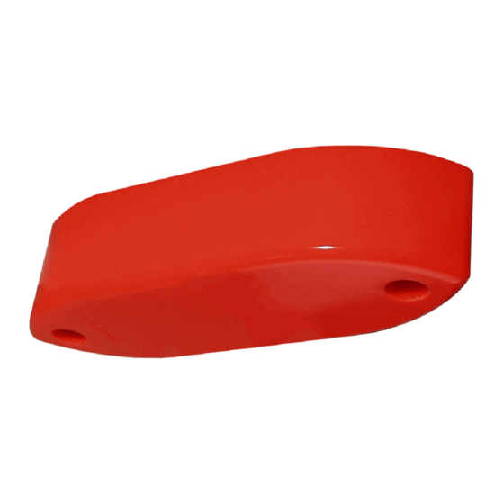
Echo sounder transducer
Hide thumbs
Also See for 50-200 COMBI D - INSTALLATION REV A:
- Datasheet (2 pages) ,
- Datasheet (2 pages) ,
- Installation manual (70 pages)

Subscribe to Our Youtube Channel
Related Manuals for Simrad 50-200 COMBI D - INSTALLATION REV A


Summary of Contents for Simrad 50-200 COMBI D - INSTALLATION REV A
- Page 1 Installation manual 50/200 Combi D Echo sounder transducer www.simrad.com M A X I M I Z I N G Y O U R P E R F O R M A N C E S E A...
- Page 3 851-165216 / Rev.A Simrad 50/200 Combi D Transducer Installation manual...
-
Page 4: About This Document
Simrad AS. The information contained in this document is subject to change without prior notice. Simrad AS shall not be liable for errors contained herein, or for incidental or consequential damages in connection with the furnishing, performance, or use of this document. -
Page 5: Transducer Installation
The next chapter in this manual provides generic guidelines for transducer installation. The drawings specific for the 50/200 Combi D transducer are located in the Drawing file. Technical specifications Refer to the 50/200 Combi D product specification, Simrad document number 855-164211. 851-165216 / Rev.A... -
Page 6: Installation
Simrad 50/200 Combi D Transducer INSTALLATION This chapter provides general installation guidelines for transducer installation. The following topics are described: • Transducer location • Mounting (different methods are shown when applicable) • Cable glands • Steel conduit for transducer cable •... -
Page 7: Transducer Location
Installation manual Transducer location General A single answer to the question where to locate the transducer cannot be given. It depends very much on the vessel’s construction. However, there are some important guide lines. Go deep The upper water layers of the sea contain a myriad of small air bubbles created by the breaking waves. -
Page 8: Boundary Water Layer
Simrad 50/200 Combi D Transducer Boundary water layer When the vessel forces its way through the sea, the friction between the hull and the water creates a boundary layer. The thickness of the boundary layer depends upon vessel speed and the roughness of the hull. -
Page 9: Propeller Noise
Installation manual Propeller noise The propulsion propeller is the dominant noise source on most fishing vessels, research vessels, merchant vessels and pleasure crafts. The noise is transmitted through the sea water. For this reason, the transducer should be placed far away from the propeller, which means on the fore part of the hull. -
Page 10: Summary And General Recommendation
Simrad 50/200 Combi D Transducer Summary and general recommendation Some of the above guide lines are conflicting, and each case has to be treated individually in order to find the best compromise. Generally the propeller noise is the dominant factor, and a... -
Page 11: External Mounting
Installation manual External mounting This transducer has a streamlined housing, and it is designed for installation outside the hull. This transducer is mainly used on smaller vessels. A location approximately 0.5 m aside from the keel may be adequate for the passage of water between the keel and the transducer. - Page 12 Simrad 50/200 Combi D Transducer Steel hull A fairing (A), made by the shipyard, is placed between the transducer and the hull. It is required in order to adapt for the deadrise angle of the hull, and it will also house a cable service loop (B).
- Page 13 Installation manual Wood or polyester hull A fairing (A), made by the shipyard, is placed between the transducer and the hull. It is required in order to adapt for the deadrise angle of the hull, and will also house a cable service loop (B).
- Page 14 Simrad 50/200 Combi D Transducer Flat hull If the vessel’s hull is flat you do not need a fairing. The transducer is then be bolted directly to the hull using two bronze or stainless steel bolts (I) and a cable bushing. Note that the...
- Page 15 Installation manual Longitudinal angle On deplacement hulls, the transducer (A) must be mounted in an angle of 5 to 8 degrees (B) in relation to the keel (C). With a planing hull, this angle must be 0 degrees. (A) = Transducer (B) = 5 to 8°...
-
Page 16: Cable Glands
Note Simrad strongly recommends that a length of conduit is fitted around transducer cable glands made of steel or bronze and extended over the water-line inside the vessel. This precaution reduces the danger of flooding in the event of gland failure and transducers installed in this manner are also easier to replace. - Page 17 (or a junction box) The gland gland kit includes all of the necessary parts needed to install the unit excluding screws. Simrad recommends that a one inch steel conduit (that the transducer cable will be run through) with an inside threaded diameter of three-quarter inches is welded to the gland’s stuffing tube.
- Page 18 Simrad 50/200 Combi D Transducer Gland installation for wood or GRP hulled vessels A bronze cable gland kit is available for wood and GRP vessels. (A) = Packing nipple. Make sure that you do not damage the transducer cable by tightening...
- Page 19 Installation manual Cable gland installation for smaller vessels This cable glands made of plastic is designed for those smaller vessels that do not need to be classified. (A) = Packing nut (bronze). Ensure that you do not to damage the transducer cable by tightening the packing nut too hard! (B) = Rubber gasket...
-
Page 20: Cable In Steel Conduit
Simrad 50/200 Combi D Transducer Cable in steel conduit It is strongly recommended to lay a steel conduit from the transducer’s cable gland to the echo sounder transceiver, and to pull the transducer cable through this conduit. There are two reasons for this. -
Page 21: Handling And Maintenance
An anti-fouling paint may be applied to the transducer face. Because some paint types may be aggressive to the polyurethane in the transducer face, please consult Simrad’s list of approved paints on the next page. Note Arctic tanks have acoustic windows made of polycarbonate. -
Page 22: Approved Anti-Fouling Paints
Simrad 50/200 Combi D Transducer Approved anti-fouling paints This is Simrad’s list of approved antifouling paints on polyurethane transducer housing. From Jotun Paints, Sandefjord Norway: • Antifouling Seamate HB 33 • Antifouling Seamate HB 66 • Antifouling Seamate HB 99 •... -
Page 23: Drawing File
These drawings are for information and guidance only. They are not in scale. All dimensions are in mm unless otherwise is noted. The drawings are available on AutoCad and/or PDF format. Contact your local Simrad dealer for assistance. → Outline drawing (830-202213), page 20 →... - Page 24 Simrad 50/200 Combi D Transducer 50/200 Combi D - Outline dimensions 851-165216 / Rev.A...
- Page 25 Installation manual 50/200 Combi D - Installation - Connections 851-165216 / Rev.A...
- Page 26 Simrad 50/200 Combi D Transducer 50/200 Combi D - Installation - Cable gland 851-165216 / Rev.A...
- Page 27 Installation manual 50/200 Combi D - Installation - Steel fairing and mounting 851-165216 / Rev.A...
- Page 28 Simrad 50/200 Combi D Transducer 50/200 Combi D - Installation - Recommended physical location 851-165216 / Rev.A...
- Page 29 Notes...
- Page 32 E 2005 Simrad AS ISBN 82-8066-058-5...
Need help?
Do you have a question about the 50-200 COMBI D - INSTALLATION REV A and is the answer not in the manual?
Questions and answers