Cisco Aironet AIR-AP1200 Hardware Installation Manual
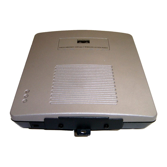
Aironet 1200 series access point
Hide thumbs
Also See for Aironet AIR-AP1200:
- Hardware installation manual (138 pages) ,
- User manual (36 pages) ,
- Ordering manual (6 pages)
Table of Contents
Advertisement
Advertisement
Table of Contents
Troubleshooting

Related Manuals for Cisco Aironet AIR-AP1200


Summary of Contents for Cisco Aironet AIR-AP1200
- Page 1 Cisco Aironet 1200 Series Access Point Hardware Installation Guide August 2005 Corporate Headquarters Cisco Systems, Inc. 170 West Tasman Drive San Jose, CA 95134-1706 http://www.cisco.com Tel: 408 526-4000 800 553-NETS (6387) Fax: 408 526-4100 Text Part Number: OL-4310-05...
- Page 2 You can determine whether your equipment is causing interference by turning it off. If the interference stops, it was probably caused by the Cisco equipment or one of its peripheral devices. If the equipment causes interference to radio or television reception, try to correct the interference by using one or more of the following measures: •...
-
Page 3: Table Of Contents
UL 2043 Certification Anti-Theft Features Network Configuration Examples Central Unit in an All-Wireless Network Root Access Point on a Wired LAN Repeater Unit that Extends Wireless Range Point-to-Point Bridge Configuration Cisco Aironet 1200 Series Access Point Hardware Installation Guide OL-4310-05... - Page 4 Understanding Express Security Settings 3-11 Using VLANs 3-11 Express Security Types 3-11 Express Security Limitations 3-12 Using the Express Security Page 3-13 Assigning an IP Address Using the CLI 3-14 Cisco Aironet 1200 Series Access Point Hardware Installation Guide OL-4310-05...
- Page 5 Mounting on a Horizontal or Vertical Surface Mounting Below a Suspended Ceiling Mounting Above a Suspended Ceiling Attaching the Access Point to the Mounting Bracket Securing the Access Point to the Mounting Bracket Cisco Aironet 1200 Series Access Point Hardware Installation Guide OL-4310-05...
- Page 6 Running the Carrier Busy Test Running the Ping or Link Test Resetting to the Default Configuration Using the MODE Button Using the Web Browser Interface Reloading the Access Point Image Using the MODE button Cisco Aironet 1200 Series Access Point Hardware Installation Guide OL-4310-05...
- Page 7 European Community, Switzerland, Norway, Iceland, and Liechtenstein Declaration of Conformity with Regard to the R&TTE Directive 1999/5/EC Declaration of Conformity for RF Exposure Guidelines for Operating Cisco Aironet Access Points in Japan Japanese Translation English Translation Administrative Rules for Cisco Aironet Access Points in Taiwan Access Points with IEEE 802.11a Radios...
- Page 8 IEEE 802.11a (5-GHz Band) Console Cable Pinouts A P P E N D I X Overview Console Port Signals and Pinouts L O S S A R Y N D E X Cisco Aironet 1200 Series Access Point Hardware Installation Guide viii OL-4310-05...
-
Page 9: Preface
This guide is for the networking professional who installs and manages the Cisco Aironet 1200 Series Access Point, hereafter referred to as the access point. To use this guide, you should have experience working with the Cisco IOS software and be familiar with the concepts and terminology of wireless local area networks. -
Page 10: Conventions
Notes, cautions, and timesavers use these conventions and symbols: Means the following will help you solve a problem. The tips information might not be troubleshooting or even an action, but could be useful information. Cisco Aironet 1200 Series Access Point Hardware Installation Guide OL-4310-05... - Page 11 La traduzione delle avvertenze riportate in questa pubblicazione si trova nell’appendice, “Translated Safety Warnings” (Traduzione delle avvertenze di sicurezza). Cisco Aironet 1200 Series Access Point Hardware Installation Guide OL-4310-05...
-
Page 12: Related Publications
• Click this link to browse to the Cisco Aironet documentation home page: http://www.cisco.com/en/US/products/hw/wireless/tsd_products_support_category_home.html To browse to the 1200 series access point documentation, click Cisco Aironet 1200 Series, which is listed under Wireless LAN Access. Obtaining Documentation Cisco documentation and additional literature are available on Cisco.com. Cisco also provides several ways to obtain technical assistance and other technical resources. -
Page 13: Cisco.com
Cisco products and to view technical documentation in HTML. With the DVD, you have access to the same documentation that is found on the Cisco website without being connected to the Internet. Certain products also have .pdf versions of the documentation available. -
Page 14: Documentation Feedback
Register to receive security information from Cisco. • A current list of security advisories and notices for Cisco products is available at this URL: http://www.cisco.com/go/psirt If you prefer to see advisories and notices as they are updated in real time, you can access a Product Security Incident Response Team Really Simple Syndication (PSIRT RSS) feed from this URL: http://www.cisco.com/en/US/products/products_psirt_rss_feed.html... -
Page 15: Obtaining Technical Assistance
Use the Cisco Product Identification (CPI) tool to locate your product serial number before submitting Note a web or phone request for service. You can access the CPI tool from the Cisco Technical Support & Documentation website by clicking the Tools & Resources link under Documentation & Tools. Choose Cisco Product Identification Tool from the Alphabetical Index drop-down list, or click the Cisco Product Identification Tool link under Alerts &... -
Page 16: Locating The Product Serial Number
Cisco engineer. The TAC Service Request Tool is located at this URL: http://www.cisco.com/techsupport/servicerequest For S1 or S2 service requests or if you do not have Internet access, contact the Cisco TAC by telephone. (S1 or S2 service requests are those in which your production network is down or severely degraded.) Cisco engineers are assigned immediately to S1 and S2 service requests to help keep your business operations running smoothly. -
Page 17: Definitions Of Service Request Severity
Obtaining Additional Publications and Information Definitions of Service Request Severity To ensure that all service requests are reported in a standard format, Cisco has established severity definitions. Severity 1 (S1)—Your network is “down,” or there is a critical impact to your business operations. You and Cisco will commit all necessary resources around the clock to resolve the situation. - Page 18 You can access the Internet Protocol Journal at this URL: http://www.cisco.com/ipj Networking products offered by Cisco Systems, as well as customer support services, can be • obtained at this URL: http://www.cisco.com/en/US/products/index.html...
-
Page 19: Chapter 1 Overview
Cisco Aironet 1200 Series Access Points provide a secure, affordable, and easy-to-use wireless LAN solution that combines mobility and flexibility with the enterprise-class features required by networking professionals. With a management system based on Cisco IOS software, the 1200 series is a Wi-Fi certified, wireless LAN transceiver. -
Page 20: Hardware Features
The 802.11b or 802.11g radio is called Radio0 and the 802.11a radio is called Radio1. Cisco Aironet CB20A client radios can sometimes fail to associate to the RM21A or RM22A radio Note modules because the CB20A client radio does not support all the channels supported by the radio modules. -
Page 21: Leds
(5805 GHz). To avoid this problem, set the channel on the RM21A or RM22A radio module to one of the channels supported by the CB20A client radio. For additional information, refer to the Cisco IOS Software Configuration Guide for Cisco Aironet Access Points. -
Page 22: Console Port
• Cisco Aironet Power Injector (AIR-PWRINJ-FIB or AIR-PWRINJ3) – A switch capable of providing inline power, such as Cisco Catalyst 3500XL, 3550, 4500, or – 6500 switches An inline power patch panel, such as the Cisco Catalyst Inline Power Patch Panel –... -
Page 23: Anti-Theft Features
Figure 1-2 shows an access point in an all-wireless network. Figure 1-2 Access Point as Central Unit in All-Wireless Network Access point Cisco Aironet 1200 Series Access Point Hardware Installation Guide OL-4310-05... -
Page 24: Root Access Point On A Wired Lan
Figure 1-3 shows access points acting as root units on a wired LAN. Figure 1-3 Access Points as Root Units on a Wired LAN Access point Access point Cisco Aironet 1200 Series Access Point Hardware Installation Guide OL-4310-05... -
Page 25: Repeater Unit That Extends Wireless Range
Figure 1-4 shows an access point acting as a repeater. Consult the Cisco IOS Software Configuration Guide for Cisco Aironet Access Points for instructions on setting up an access point as a repeater. Non-Cisco client devices might have difficulty communicating with repeater access points. -
Page 26: Workgroup Bridge Configuration
Figure 1-6, the unit is configured in workgroup bridge mode and is associated to a Cisco Aironet access point as a wireless client device. This configuration enables the Ethernet-enabled devices to pass Ethernet traffic to and from the main LAN using the workgroup bridge. -
Page 27: Installing The Access Point
Basic Installation Guidelines, page 2-3 Before Beginning the Installation, page 2-4 • Installation Summary, page 2-6 • Connecting the 2.4-GHz Antennas, page 2-6 • Connecting the Ethernet and Power Cables, page 2-8 • Cisco Aironet 1200 Series Access Point Hardware Installation Guide OL-4310-05... -
Page 28: Chapter 2 Installing The Acces Point
(RF) electromagnetic energy emitted by FCC certified equipment. When used with approved Cisco Aironet antennas, Cisco Aironet products meet the uncontrolled environmental limits found in OET-65 and ANSI C95.1, 1991. Proper installation of this radio according to the instructions found in this manual will result in user exposure that is substantially below the FCC recommended limits. -
Page 29: Unpacking The Access Point
Ensure that all items listed in the “Package Contents” section are included in the shipment. Check each Step 3 item for damage. If any item is damaged or missing, notify your authorized Cisco sales representative. Package Contents Each access point package contains the following items: Cisco Aironet 1200 Series Access Point •... -
Page 30: Installation Above Suspended Ceilings
UL 2043 and they should not be placed in a building’s environmental air space, such as above suspended ceilings. If you plan to mount the access point with a 5-GHz radio in environmental air space, Cisco recommends Note that you mount the access point horizontally with its antennas pointing down. - Page 31 Right 5-GHz antenna connector (RP-TNC) Blue 5-GHz label 5-GHz radio Module mounting screws Only connect Cisco 5-GHz antennas with blue labels or blue dots to the RM22A radio module. Note Cisco Aironet 1200 Series Access Point Hardware Installation Guide OL-4310-05...
-
Page 32: Installation Summary
If you are using two antennas for diversity coverage, attach the second antenna or antenna cable to the 2.4-GHz Left (RP-TNC) antenna connector. Step 2 If you are using a Cisco Aironet 2 dBi antenna, orient the antenna depending on how you intend to mount the access point. •... -
Page 33: Connecting The 5-Ghz External Antennas
If you are using two antennas for diversity coverage, attach the second antenna cable to the Left 5-GHz (RP-TNC) antenna connector. The Cisco Aironet antennas have a blue marker label or blue dot near the antenna connector and Note the radio module has a corresponding blue label near the 5-GHz antenna connectors. -
Page 34: Connecting The Ethernet And Power Cables
Access Point Option 4 The access point power options are listed below: A switch with inline power, such as a Cisco Catalyst 3500XL, 3550-24 PWR, 4000, or 6500 switch • A Cisco Aironet Power Injector (AIR-PWRINJ-FIB or AIR-PWRINJ3) •... -
Page 35: Connecting To An Ethernet Network With An Inline Power Source
If you use a power supply or power injector to power the access point, you must use the power supply Note included with your access point and the Cisco Aironet Power Injector for the 1100 and 1200 series access points. -
Page 36: Powering Up The Access Point
When the sequence is complete, you are ready to obtain the access point’s IP address and perform an initial configuration. Refer to Chapter 3, “Configuring the Access Point for the First Time,” instructions on assigning basic settings to the access point. Cisco Aironet 1200 Series Access Point Hardware Installation Guide 2-10 OL-4310-05... - Page 37 Assigning Basic Settings, page 3-4 • • Configuring Basic Security Settings, page 3-9 Assigning an IP Address Using the CLI, page 3-14 • • Using a Telnet Session to Access the CLI, page 3-14 Cisco Aironet 1200 Series Access Point Hardware Installation Guide OL-4310-05...
-
Page 38: Before You Start
Enter your username in the User Name field. The default username is Cisco. Step 3 Step 4 Enter the access point password in the Password field and press Enter. The default password is Cisco. The Summary Status page appears. Step 5 Click System Software and the System Software screen appears. -
Page 39: Default Ip Address Behavior
Note Default IP Address Behavior When you connect a 1200 series access point running Cisco IOS Release 12.3(2)JA or later software with a default configuration to your LAN, the access point requests an IP address from your DHCP server and, if it does not receive an IP address, continues to send requests indefinitely. -
Page 40: Connecting To The Access Point Locally
DB-9 to RJ-45 RJ-45 serial serial cable connector The Cisco part number for the DB-9 to RJ-45 serial cable is AIR-CONCAB1200. Browse to Note http://www.cisco.com/go/marketplace to order a serial cable. Set up a terminal emulator to communicate with the access point. Use the following settings for the Step 2 terminal emulator connection: 9600 baud, 8 data bits, no parity, 1 stop bit, and no flow control. - Page 41 Password screen appears. Press Tab to bypass the Username field and advance to the Password field. Step 3 Enter the case-sensitive password Cisco and press Enter. The Summary Status page appears. Figure 3-2 Step 4 shows the Summary Status page.
-
Page 42: Assigning Basic Settings
DHCP—IP addresses are automatically assigned by your network’s DHCP server. – Static IP—The access point uses a static IP address that you enter in the IP address field. – Cisco Aironet 1200 Series Access Point Hardware Installation Guide OL-4310-05... - Page 43 Root Bridge—Specifies that the unit is operating as a root bridge and connects directly to the – main Ethernet LAN network. In this mode, the unit accepts an association from another Cisco Aironet non-root bridge. In bridge mode (root or non-root), the unit cannot communicate with Cisco Aironet 1400 Note Series Outdoor Bridges.
-
Page 44: Default Settings On The Express Setup Page
Settings page. Clicking Custom takes you to the Network Interfaces: Radio-802.11b Settings page. Aironet Extensions—Enable this setting (for each radio interface) if there are only Cisco Aironet • devices on your wireless LAN or the unit is configured in repeater mode. -
Page 45: Enabling The Radio Interfaces
1. If a 1200 series access point running Cisco IOS Release 12.3(2)JA or later software with a default configuration does not receive an IP address from your DHCP server, it continues to send DHCP requests indefinitely. Enabling the Radio Interfaces In Cisco IOS Release 12.3(4)JA and later, the access point radios are disabled by default, and there is no... - Page 46 Chapter 3 Configuring the Access Point for the First Time Configuring Basic Security Settings Figure 3-4 shows the Express Security page. Figure 3-4 Express Security Page Cisco Aironet 1200 Series Access Point Hardware Installation Guide 3-10 OL-4310-05...
-
Page 47: Understanding Express Security Settings
SSID table at the bottom of the page. You can create up to 16 SSIDs on the access point. In Cisco IOS Release 12.3(4)JA and later, there is no default SSID. You must configure an SSID before Note client devices can associate to the access point. -
Page 48: Express Security Limitations
• address authentication and EAP authentication). To configure combinations of authentication types, use the Security SSID Manager page. For detailed information about security and security settings, refer to the Cisco IOS Software Note Configuration Guide for Cisco Aironet Access Points. -
Page 49: Using The Express Security Page
If you do not use VLANs on your wireless LAN, the security options that you can assign to Note multiple SSIDs are limited. Refer to the Cisco IOS Software Configuration Guide for Cisco Aironet Access Points for VLAN details. Step 6 Click Apply. -
Page 50: Assigning An Ip Address Using The Cli
Windows 2000, type open followed by the access point’s IP address. Step 3 In the Host Name field, type the access point’s IP address and click Connect. Cisco Aironet 1200 Series Access Point Hardware Installation Guide 3-14 OL-4310-05... - Page 51 The access point web-browser interface is fully compatible with Microsoft Internet Explorer version 6.0 on Windows 98 and 2000 platforms, and with Netscape version 7.0 on Windows 98, Windows 2000, and Solaris platforms. Cisco Aironet 1200 Series Access Point Hardware Installation Guide OL-4310-05...
-
Page 52: Using The Web-Browser Interface For The First Time
Back button returns you to the previous page without saving any changes you have made. Clicking Cancel cancels any changes you made on the page and keeps you on that page. Cisco Aironet 1200 Series Access Point Hardware Installation Guide OL-4310-05... -
Page 53: Chapter 4 Using The Web-Browser Interface
Chapter 4 Using the Web-Browser Interface Using the Management Pages in the Web-Browser Interface Figure 4-1 shows the web-browser interface home page. Figure 4-1 Web-Browser Interface Home Page Cisco Aironet 1200 Series Access Point Hardware Installation Guide OL-4310-05... -
Page 54: Using Action Buttons
Updates status information or statistics displayed on a page. Cancel Discards changes to the page and remains on the page. Back Discards any changes made to the page and returns to the previous page. Cisco Aironet 1200 Series Access Point Hardware Installation Guide OL-4310-05... -
Page 55: Character Restrictions In Entry Fields
Using the Web-Browser Interface Using Online Help Character Restrictions in Entry Fields Because the 1200 series access point uses Cisco IOS software, there are certain characters that you cannot use in the entry fields on the web-browser interface. Table 4-2 lists the prohibited characters and the fields in which you cannot use them. - Page 56 Chapter 4 Using the Web-Browser Interface Using Online Help Cisco Aironet 1200 Series Access Point Hardware Installation Guide OL-4310-05...
- Page 57 C H A P T E R Using the Command-Line Interface This chapter describes the Cisco IOS command-line interface (CLI) that you can use to configure your access point. It contains these sections: Cisco IOS Command Modes, page 5-2 •...
-
Page 58: Cisco Ios Command Modes
Cisco IOS Command Modes The Cisco IOS user interface is divided into many different modes. The commands available to you depend on which mode you are currently in. Enter a question mark (?) at the system prompt to obtain a list of commands available for each command mode. -
Page 59: C H A P T E R 5 Using The Command-Line Interface
For example, the no shutdown interface configuration command reverses the shutdown of an interface. Use the command without the keyword no to re-enable a disabled feature or to enable a feature that is disabled by default. Cisco Aironet 1200 Series Access Point Hardware Installation Guide OL-4310-05... -
Page 60: Understanding Cli Messages
Using Command History The Cisco IOS provides a history or record of commands that you have entered. This feature is particularly useful for recalling long or complex commands or entries, including access lists. You can customize the command history feature to suit your needs as described in these sections: •... -
Page 61: Recalling Commands
This section describes the editing features that can help you manipulate the command line. It contains these sections: Enabling and Disabling Editing Features, page 5-6 • Editing Commands Through Keystrokes, page 5-6 • Editing Command Lines that Wrap, page 5-7 • Cisco Aironet 1200 Series Access Point Hardware Installation Guide OL-4310-05... -
Page 62: Enabling And Disabling Editing Features
Delete all characters from the cursor to the beginning of the command line. Ctrl-W Delete the word to the left of the cursor. Esc D Delete from the cursor to the end of the word. Cisco Aironet 1200 Series Access Point Hardware Installation Guide OL-4310-05... -
Page 63: Editing Command Lines That Wrap
101 permit tcp 131.108.2.5 255.255.255.0 131.108.1 ap(config)# $ 101 permit tcp 131.108.2.5 255.255.255.0 131.108.1.20 255.25 ap(config)# $t tcp 131.108.2.5 255.255.255.0 131.108.1.20 255.255.255.0 eq ap(config)# $108.2.5 255.255.255.0 131.108.1.20 255.255.255.0 eq 45 Cisco Aironet 1200 Series Access Point Hardware Installation Guide OL-4310-05... -
Page 64: Searching And Filtering Output Of Show And More Commands
If Telnet is not listed in your Accessories menu, select Start > Run, type Telnet in the entry field, and press Enter. When the Telnet window appears, click Connect and select Remote System. Step 2 Cisco Aironet 1200 Series Access Point Hardware Installation Guide OL-4310-05... -
Page 65: Opening The Cli With Secure Shell
At the username and password prompts, enter your administrator username and password. The default Step 4 username is Cisco, and the default password is Cisco. The default enable password is also Cisco. Usernames and passwords are case-sensitive. Opening the CLI with Secure Shell Secure Shell Protocol is a protocol that provides a secure, remote connection to networking devices set up to use it. - Page 66 Chapter 5 Using the Command-Line Interface Accessing the CLI Cisco Aironet 1200 Series Access Point Hardware Installation Guide 5-10 OL-4310-05...
- Page 67 • Mounting Above a Suspended Ceiling, page 6-5 Attaching the Access Point to the Mounting Bracket, page 6-7 • • Securing the Access Point to the Mounting Bracket, page 6-7 Cisco Aironet 1200 Series Access Point Hardware Installation Guide OL-4310-05...
-
Page 68: Mounting Instructions
UL 2043 and they should not be placed in a building’s environmental air space, such as above suspended ceilings. If you plan to mount the access point in environmental air space and will upgrade to a 5-GHz radio, Cisco Note recommends that you mount the access point horizontally with its antennas pointing down. -
Page 69: Mounting On A Horizontal Or Vertical Surface
Attach the access point to the mounting bracket. Step 5 You can make your installation more secure by mounting it to a stud or major structural member Note and using the appropriate fasteners. Cisco Aironet 1200 Series Access Point Hardware Installation Guide OL-4310-05... -
Page 70: Mounting Below A Suspended Ceiling
Install a plastic spacer on each T-rail clip stud. The spacer’s legs should contact the suspended ceiling Step 5 T-rail. Attach the mounting bracket to the T-rail clip studs and start a Keps nut on each stud. Step 6 Cisco Aironet 1200 Series Access Point Hardware Installation Guide OL-4310-05... -
Page 71: Mounting Above A Suspended Ceiling
It may be helpful to refer to Figure 6-3 before proceeding. Figure 6-3 Mounting Bracket Parts Suspended ceiling T-rail Bracket mounting clip T-rail clip Access point mounting bracket Height adjustment screw Access point T-bar box hanger Cisco Aironet 1200 Series Access Point Hardware Installation Guide OL-4310-05... - Page 72 Orient the access point 2-GHz antennas so that they are pointing down when mounted on the T-bar Box Step 4 hanger. Orient the 5-GHz antenna for patch or omnidirectional operation as desired. Cisco Aironet 1200 Series Access Point Hardware Installation Guide OL-4310-05...
-
Page 73: Attaching The Access Point To The Mounting Bracket
When the access point is properly installed on the mounting bracket, the holes in the security hasps line up so you can install a padlock. Known compatible padlocks are Master Lock models 120T or 121T. Cisco Aironet 1200 Series Access Point Hardware Installation Guide OL-4310-05... - Page 74 Chapter 6 Mounting Instructions Securing the Access Point to the Mounting Bracket Cisco Aironet 1200 Series Access Point Hardware Installation Guide OL-4310-05...
- Page 75 • • Removing a Blank Spacer Card, page 7-4 Removing a 2.4-GHz Radio, page 7-5 • • Installing a 2.4-GHz Radio, page 7-7 Finding the Software Version, page 7-10 • Cisco Aironet 1200 Series Access Point Hardware Installation Guide OL-4310-05...
-
Page 76: Chapter 7 2.4-Ghz Radio Upgrade
ESD-protected workstation. Note After you install the new radio, all configurable radio settings will be at default values. Refer to the Cisco IOS Software Configuration Guide for Cisco Aironet Access Points for complete instructions on configuring the new radio. -
Page 77: Opening The Access Cover
If your access point was not configured with a 2.4-GHz radio, go to the “Removing a Blank Spacer Card” section. If you are replacing an existing 2.4-GHz radio, go to the “Removing a 2.4-GHz Radio” section. Cisco Aironet 1200 Series Access Point Hardware Installation Guide OL-4310-05... -
Page 78: Removing A Blank Spacer Card
Card-retaining clips Antenna connector (black wire) Antenna connector (white wire) Carefully bend the card near the slots in opposite directions to provide enough clearance to remove the Step 2 antenna wires. Cisco Aironet 1200 Series Access Point Hardware Installation Guide OL-4310-05... -
Page 79: Removing A 2.4-Ghz Radio
The antenna connectors can be damaged by using a pair of long-nose pliers during the removal Caution process. To avoid damaging the antenna wire assemblies, handle them by their connectors. Caution Cisco Aironet 1200 Series Access Point Hardware Installation Guide OL-4310-05... - Page 80 Remove the 2.4-GHz card from the mini-PCI connector. Place the removed 2.4GHz radio card into an anti-static bag. Step 3 For instructions on installing a new radio card, go to the “Installing a 2.4-GHz Radio” section. Cisco Aironet 1200 Series Access Point Hardware Installation Guide OL-4310-05...
-
Page 81: Installing A 2.4-Ghz Radio
The internal access point components and the 2.4-GHz radio can be damaged by ESD from improper Caution handling. Carefully remove the Cisco Aironet 2.4-GHz radio card from its anti-static bag. Step 1 Grasp the radio card only on the edges, being careful not to touch components on the board or the gold Step 2 connector pins. - Page 82 Look at the compliance labels on your access point. Depending on the model you originally ordered, Step 9 there may be up to three labels affixed to the case. Cisco Aironet 1200 Series Access Point Hardware Installation Guide OL-4310-05...
-
Page 83: Attaching The Compliance Labels
Make sure that your access point has the correct labels after you install or upgrade its radio configuration so that it will be in compliance with regulations in your country. Cisco Aironet 1200 Series Access Point Hardware Installation Guide OL-4310-05... -
Page 84: Placing The Labels
Discard any labels that you did not use. The radio card installation is now complete. To configure the radio with your wireless network settings, refer to the Cisco IOS Software Configuration Guide for Cisco Aironet Access Points. Finding the Software Version To find the version of IOS software running on your access point, use a Telnet session to log into the access point and enter the show version EXEC command. - Page 85 Upgrade Overview, page 8-2 • Removing the 5-GHz Radio Access Cover, page 8-2 • • Removing a 5-GHz Radio Module, page 8-3 Installing a 5-GHz Radio Module, page 8-5 • Cisco Aironet 1200 Series Access Point Hardware Installation Guide OL-4310-05...
-
Page 86: Chapter 8 5-Ghz Radio Module Upgrade
Install the new 5-GHz radio module. Caution Your access point must be running Cisco IOS Release 12.3(2)JA or later before you upgrade to the RM21A or RM22A radio module; otherwise your access point may not be able to complete the boot sequence until the radio is removed. -
Page 87: Removing A 5-Ghz Radio Module
5-GHz Radio Module Mounting screws Access point 5-GHz radio module antenna Do not attempt to remove the mounting screws from the module; they are captured in the module Note housing. Cisco Aironet 1200 Series Access Point Hardware Installation Guide OL-4310-05... - Page 88 For a radio module with connectors, insert the radio module into a static protected bag. To install a new 5-GHz radio module, see the “Installing a 5-GHz Radio Module” section on page 8-5. Cisco Aironet 1200 Series Access Point Hardware Installation Guide OL-4310-05...
-
Page 89: Installing A 5-Ghz Radio Module
Installing a 5-GHz Radio Module (RM20A or RM21A Shown) Access point Access point card-bus slot 5-GHz radio module antenna 5-GHz radio card Step 4 Push the 5-GHz radio module into the slot until you hear a slight click. Cisco Aironet 1200 Series Access Point Hardware Installation Guide OL-4310-05... - Page 90 The RM22A radio module has the same mounting screws as the RM20A radio module. Note Figure 8-5 Location of Mounting Screws (RM20A or RM21A) Shown) 5-GHz radio module antenna Mounting screws Cisco Aironet 1200 Series Access Point Hardware Installation Guide OL-4310-05...
-
Page 91: Attaching The Compliance Label
• Table 8-1 shows where to place the labels on your 1200 series access point, based on the model you are upgrading. Follow these steps to place the labels correctly: Cisco Aironet 1200 Series Access Point Hardware Installation Guide OL-4310-05... -
Page 92: Finding The Software Version
Step 4 The 5-GHz radio module installation is now complete and radio settings are at default values. To configure the 5-GHz radio with your wireless network settings refer to the Cisco IOS Software Configuration Guide for Cisco Aironet Access Points. -
Page 93: Troubleshooting
C H A P T E R Troubleshooting This chapter provides troubleshooting procedures for basic problems with the access point. For the most up-to-date, detailed troubleshooting information, refer to the Cisco Technical Support and Documentation website at the following URL: http://www.cisco.com/en/US/products/hw/wireless/tsd_products_support_category_home.html... -
Page 94: Chapter 9 Troubleshooting
The radio LED blinks green to indicate radio traffic activity. The light is normally off, but it blinks • green whenever a packet is received or transmitted over the access point’s radio. Cisco Aironet 1200 Series Access Point Hardware Installation Guide OL-4310-05... - Page 95 Configuration – Amber – Resetting the configuration options to Reset factory defaults. Failure Firmware failure; try disconnecting and reconnecting unit power. Firmware – – Loading new firmware image. Upgrade Cisco Aironet 1200 Series Access Point Hardware Installation Guide OL-4310-05...
-
Page 96: Checking Basic Settings
Enabling the Radio Interfaces In Cisco IOS Release 12.3(4)JA and later, the access point radios are disabled by default, and there is no default SSID. You must create an SSID and enable the radios before the access point will allow wireless associations from other devices. -
Page 97: Ssid
If a client device’s SSID does not match the SSID of an access point in radio range, the client device will not associate. In Cisco IOS Release 12.3(2)JA2 and earlier, the access point default SSID is tsunami. In Cisco IOS Release 12.3(4)JA and later, there is no default SSID. You must configure an SSID before Note client devices can associate to the access point. -
Page 98: Running The Ping Or Link Test
If you want to specify the number of packets to use in the test, follow these steps: Enter a number of packets in the Number of Packets field Enter a packet size in the Packet Size field. Cisco Aironet 1200 Series Access Point Hardware Installation Guide OL-4310-05... -
Page 99: Resetting To The Default Configuration
Telnet interface, or Cisco IOS commands. Note The access point is configured with the factory default values including the IP address (set to receive an IP address using DHCP). Cisco Aironet 1200 Series Access Point Hardware Installation Guide OL-4310-05... -
Page 100: Using The Web Browser Interface
However, you can use the MODE button when the access point has a corrupt firmware image. Caution Your access point must be running specific Cisco IOS software releases before you upgrade its radios; otherwise, your access point might not be able to complete the boot sequence until the radio is removed (see Table 9-3). -
Page 101: Using The Mode Button
You can also use the Web browser interface to reload the access point image file. The Web browser interface supports loading the image file using HTTP or TFTP interfaces. Your access point configuration is not changed when using the browser to reload the image file. Note Cisco Aironet 1200 Series Access Point Hardware Installation Guide OL-4310-05... -
Page 102: Browser Http Interface
Click the System Software tab and then click Software Upgrade. The HTTP Upgrade screen appears. Step 5 Click the TFTP Upgrade tab. Step 6 Enter the IP address for the TFTP server in the TFTP Server field. Step 7 Cisco Aironet 1200 Series Access Point Hardware Installation Guide 9-10 OL-4310-05... -
Page 103: Obtaining The Access Point Image File
For additional information click the Help icon on the Software Upgrade screen. Obtaining the Access Point Image File Your access point must be running specific Cisco IOS software releases before you upgrade its radios; Caution otherwise your access point might not be able to complete the boot sequence until the radio is removed... -
Page 104: Obtaining The Tftp Server Software
Troubleshooting Obtaining the TFTP Server Software Obtaining the TFTP Server Software You can download TFTP server software from several web sites. Cisco recommends the shareware TFTP utility available at this URL: http://tftpd32.jounin.net Follow the instructions on the website for installing and using the utility. -
Page 105: Appendix
Statement 332—Antenna Installation Warning, page A-3 • Statement 1001—Work During Lightning Activity Warning, page A-4 • • Statement 1004—Installation Instructions Warning, page A-5 Statement 1005—Circuit Breaker (20A) Warning, page A-6 • Cisco Aironet 1200 Series Access Point Hardware Installation Guide OL-4310-05... -
Page 106: Appendix A Translated Safety Warning
Varning! Använd inte den trådlösa nätverksenheten i närheten av oskyddade tändhattar eller i en explosiv miljö om inte enheten modifierats för att kunna användas i sådana sammanhang. Cisco Aironet 1200 Series Access Point Hardware Installation Guide OL-4310-05... -
Page 107: Statement 332-Antenna Installation Warning
Comunicaciones (FCC) es preciso ubicar las antenas a un mínimo de 20 cm (7,9 pulgadas) o más del cuerpo de las personas. Varning! För att följa FCC-exponeringsgränserna för radiofrekvens (RF), bör antenner placeras på minst 20 cm avstånd från alla människor. Cisco Aironet 1200 Series Access Point Hardware Installation Guide OL-4310-05... -
Page 108: Statement 1001-Work During Lightning Activity Warning
No operar el sistema ni conectar o desconectar cables durante el transcurso de descargas eléctricas en la atmósfera. Varning! Vid åska skall du aldrig utföra arbete på systemet eller ansluta eller koppla loss kablar. Cisco Aironet 1200 Series Access Point Hardware Installation Guide OL-4310-05... -
Page 109: Statement 1004-Installation Instructions Warning
Leia as instruções de instalação antes de ligar o sistema à fonte de energia. ¡Advertencia! Lea las instrucciones de instalación antes de conectar el sistema a la red de alimentación. Varning! Läs installationsanvisningarna innan du kopplar systemet till strömförsörjningsenheten. Cisco Aironet 1200 Series Access Point Hardware Installation Guide OL-4310-05... -
Page 110: Statement 1005-Circuit Breaker (20A) Warning
Este equipo utiliza el sistema de protección contra cortocircuitos (o sobrecorrientes) del edificio. Asegúrese de que el dispositivo de protección no sea superior a: Varning! Denna produkt är beroende av i byggnaden installerat kortslutningsskydd (överströmsskydd). Kontrollera att skyddsanordningen inte har högre märkvärde än: Cisco Aironet 1200 Series Access Point Hardware Installation Guide OL-4310-05... - Page 111 Appendix A Translated Safety Warnings Statement 1005—Circuit Breaker (20A) Warning Cisco Aironet 1200 Series Access Point Hardware Installation Guide OL-4310-05...
- Page 112 Appendix A Translated Safety Warnings Statement 1005—Circuit Breaker (20A) Warning Cisco Aironet 1200 Series Access Point Hardware Installation Guide OL-4310-05...
-
Page 113: Appendix
A P P E N D I X Declarations of Conformity and Regulatory Information This appendix provides declarations of conformity and regulatory information for the Cisco Aironet 1200 Series Access Points. This appendix contains the following sections: • Manufacturers Federal Communication Commission Declaration of Conformity Statement Department of Communications—Canada... -
Page 114: A P P E N D I X B Declarations Of Conformity And Regulatory Information
Increase separation between the equipment and receiver. • Connect the equipment to an outlet on a circuit different from which the receiver is connected. • Consult the dealer or an experienced radio/TV technician. • Cisco Aironet 1200 Series Access Point Hardware Installation Guide OL-4310-05... -
Page 115: Department Of Communications-Canada
B-1. Any changes or modification to the product not expressly approved by Cisco could void the user’s authority to operate this device. Within the 5.15 to 5.25 GHz band (5 GHz radio channels 34 to 48) the U-NII devices are restricted to... -
Page 116: European Community, Switzerland, Norway, Iceland, And Liechtenstein
Declarations of Conformity and Regulatory Information European Community, Switzerland, Norway, Iceland, and Liechtenstein Cisco Aironet 2.4-GHz Access Points are certified to the requirements of RSS-210 for 2.4-GHz spread spectrum devices, and Cisco Aironet 54-Mbps, 5-GHz Access Points are certified to the requirements of RSS-210 for 5-GHz spread spectrum devices.The use of this device in a system operating either partially... - Page 117 The following CE mark is affixed to access points with a 2.4 GHz radio: This equipment is intended to be used in all EU and EFTA countries. Outdoor use may be restricted to Note certain frequencies and/or may require a license for operation. For more details, contact Cisco Corporate Compliance. Note...
-
Page 118: Declaration Of Conformity For Rf Exposure
Dual antennas used for diversity operation are not considered co-located. Note Guidelines for Operating Cisco Aironet Access Points in Japan This section provides guidelines for avoiding interference when operating Cisco Aironet access points in Japan. These guidelines are provided in both Japanese and English. Japanese Translation... -
Page 119: English Translation
Contact Number: 03-5549-6500 Administrative Rules for Cisco Aironet Access Points in Taiwan This section provides administrative rules for operating Cisco Aironet access points inTaiwan. The rules are provided in both Chinese and English. Access Points with IEEE 802.11a Radios... -
Page 120: All Access Points
Appendix B Declarations of Conformity and Regulatory Information Administrative Rules for Cisco Aironet Access Points in Taiwan All Access Points Chinese Translation English Translation Administrative Rules for Low-power Radio-Frequency Devices Article 12 For those low-power radio-frequency devices that have already received a type-approval, companies, business units or users should not change its frequencies, increase its power or change its original features and functions. -
Page 121: Operation Of Cisco Aironet Access Points In Brazil
Declarations of Conformity and Regulatory Information Operation of Cisco Aironet Access Points in Brazil Operation of Cisco Aironet Access Points in Brazil This section contains special information for operation of Cisco Aironet access points in Brazil. Access Point Model AIR-AP1231G-A-K9... -
Page 122: Declaration Of Conformity Statements
All the Declaration of Conformity statements related to this product can be found at the following URL: http://www.ciscofax.com Declaration of Conformity Statements for European Union Countries The Declaration of Conformity statements for the European Union countries are listed below: Cisco Aironet 1200 Series Access Point Hardware Installation Guide B-10 OL-4310-05... - Page 123 Appendix B Declarations of Conformity and Regulatory Information Declaration of Conformity Statements for European Union Countries Cisco Aironet 1200 Series Access Point Hardware Installation Guide B-11 OL-4310-05...
- Page 124 Appendix B Declarations of Conformity and Regulatory Information Declaration of Conformity Statements for European Union Countries Cisco Aironet 1200 Series Access Point Hardware Installation Guide B-12 OL-4310-05...
- Page 125 Appendix B Declarations of Conformity and Regulatory Information Declaration of Conformity Statements for European Union Countries Cisco Aironet 1200 Series Access Point Hardware Installation Guide B-13 OL-4310-05...
- Page 126 Appendix B Declarations of Conformity and Regulatory Information Declaration of Conformity Statements for European Union Countries Cisco Aironet 1200 Series Access Point Hardware Installation Guide B-14 OL-4310-05...
- Page 127 Appendix B Declarations of Conformity and Regulatory Information Declaration of Conformity Statements for European Union Countries Cisco Aironet 1200 Series Access Point Hardware Installation Guide B-15 OL-4310-05...
-
Page 128: Declaration Of Conformity
San Jose, CA 95134 - USA Declare under our sole responsibility that the product, AIR-RM21A-E-K9 Product: Cisco Aironet RM21 Series 5 GHz 54 Mbps Wireless LAN Module AIR-RM22A-E-K9 Variant: Cisco Aironet RM22 Series 5 GHz 54 Mbps Wireless LAN Module... - Page 129 San Jose, CA 95134 - USA Additional information: EMC Test Report: Cisco Systems EDCS-366871 Safety Test Report: CCS: 04U2586-5; UL: E-145532-V26-S8 Radio Test Report: CCS: 03U2409-5 (2.4 GHz) & 04U2586-8 (5 GHz) DofC 441918 Cisco Aironet 1200 Series Access Point Hardware Installation Guide B-17 OL-4310-05...
- Page 130 Appendix B Declarations of Conformity and Regulatory Information Declaration of Conformity Statements for European Union Countries Cisco Aironet 1200 Series Access Point Hardware Installation Guide B-18 OL-4310-05...
-
Page 131: Appendix
A P P E N D I X Access Point Specifications This appendix provides technical specifications for the Cisco Aironet 1200 Series Access Point. Table C-1 lists the technical specifications for the access point. Table C-1 Access Point Specifications Category Access Point with 802.11b or 802.11g Radio... - Page 132 1.97 lbs (0.89 kg) with RM20A or RM21A radio module and 802.11b or 802.11g radio 1.83 lbs (0.83 kg) with RM22A radio module 1.93 lbs (0.88 kg) with RM22A radio module and 802.11b or 802.11g radio Cisco Aironet 1200 Series Access Point Hardware Installation Guide OL-4310-05...
- Page 133 5 dBi omnidirectional gain or 9 dBi directional gain depending on the positioning of the antenna assembly. RM22A radio module: A diversity system with two RP-TNC antenna connectors for external antennas (Cisco antennas are sold separately). Cisco Aironet 1200 Series Access Point Hardware Installation Guide OL-4310-05...
- Page 134 6, 9, 12, 18, 24, 36, 48, and 54 Mbps 1, 2, 5.5, and 11 Mbps 802.11g radio: 1, 2, 5.5, and 11 Mbps 6, 9, 12, 18, 24, 36, 48, and 54 Mbps Cisco Aironet 1200 Series Access Point Hardware Installation Guide OL-4310-05...
- Page 135 1300 ft (396.2 m) at 6 Mbps 600 ft (182.9 m) at 18 Mbps 250 ft (76.2 m) at 54 Mbps Note Using 2.2dBi antennas at the access point and the client adapter. Cisco Aironet 1200 Series Access Point Hardware Installation Guide OL-4310-05...
- Page 136 Note If you plan to mount the access point in environmental air space using a 802.11a radio, Cisco recommends that you mount the access point horizontally with its antennas pointing down. Doing so results in the access point complying with regulatory requirements for environmental air space with an 802.11a radio installed.
-
Page 137: Appendix
The following topics are covered in this appendix: Channels, page D-2 • • Maximum Power Levels and Antenna Gains, page D-6 Cisco Aironet 1200 Series Access Point Hardware Installation Guide OL-4310-05... -
Page 138: Ieee 802.11B (2.4-Ghz Band
9 through 11 can be used indoors and outdoors. Users are responsible for ensuring that the channel set configuration is in compliance with the regulatory standards of Mexico. Cisco Aironet 1200 Series Access Point Hardware Installation Guide OL-4310-05... -
Page 139: Ieee 802.11G (2.4-Ghz Band
9 through 11 can be used indoors and outdoors. Users are responsible for ensuring that the channel set configuration is in compliance with the regulatory standards of Mexico. Cisco Aironet 1200 Series Access Point Hardware Installation Guide OL-4310-05... -
Page 140: Ieee 802.11A (5-Ghz Band
– 5200 – – 5210 – – – 5220 – – 5230 – – – 5240 – – 5260 – – 5280 – – 5300 – – 5320 – – Cisco Aironet 1200 Series Access Point Hardware Installation Guide OL-4310-05... - Page 141 2. In Autralia and New Zealand, the AIR-RM22A-N-K9 is approved only with antenna gains of 6 dBi or less. 3. Requires Cisco IOS Release 12.3(7)JA or later. 4. Requires Cisco IOS Release 12.3(4)JA or later. Cisco Aironet 1200 Series Access Point Hardware Installation Guide OL-4310-05...
-
Page 142: Maximum Power Levels And Antenna Gains
(4 W EIRP maximum) 13.5 China (–C) (10 mW EIRP maximum) EMEA (–E) (100 mW EIRP maximum) 13.5 Israel (–I) (100 mW EIRP maximum) 13.5 Japan (–J) (10 mW/MHz EIRP maximum) 13.5 Cisco Aironet 1200 Series Access Point Hardware Installation Guide OL-4310-05... - Page 143 OFDM Modulation Americas (–A) (4 W EIRP maximum) EMEA (–E) (100 mW EIRP maximum) Israel (–I) (100 mW EIRP maximum) Japan (–J) (10 mW/MHz EIRP maximum) – – – – Cisco Aironet 1200 Series Access Point Hardware Installation Guide OL-4310-05...
- Page 144 (800 mW EIRP maximum) The maximum power level for Chile is 20 mW. When operating in Chile, you must ensure that your Note access point Transmitter Power setting never exceeds 20 mW. Cisco Aironet 1200 Series Access Point Hardware Installation Guide OL-4310-05...
- Page 145 5805 – – – – 5825 – – – – – – – – – – 1. Requires Cisco IOS Release 12.3(7)JA. 2. Requires Cisco IOS Release 12.3(4)JA or later. Cisco Aironet 1200 Series Access Point Hardware Installation Guide OL-4310-05...
- Page 146 – – – – 5825 – – – – – – – – – – 1. Requires Cisco IOS Release 12.3(7)JA. 2. Requires Cisco IOS Release 12.3(4)JA or later. Cisco Aironet 1200 Series Access Point Hardware Installation Guide D-10 OL-4310-05...
- Page 147 2. In South Korea, the AIR-RM22A-N-K9 is approved only with antenna gains of 6 dBi or less. 3. Requires Cisco IOS Release 12.3(7)JA. 4. Requires Cisco IOS Release 12.3(4)JA or later. Cisco Aironet 1200 Series Access Point Hardware Installation Guide D-11 OL-4310-05...
- Page 148 – – – 5785 – – – – – 5805 – – – – – 5825 – – – – – 1. Requires Cisco IOS Release 12.3(4)JA or later. Cisco Aironet 1200 Series Access Point Hardware Installation Guide D-12 OL-4310-05...
-
Page 149: Appendix
This appendix identifies the pinouts for the serial console cable that connects to the access point’s serial console port. The appendix contains the following sections: Overview, page E-2 • Console Port Signals and Pinouts, page E-2 • Cisco Aironet 1200 Series Access Point Hardware Installation Guide OL-4310-05... -
Page 150: Overview
The access point requires a special serial cable that connects the access point serial console port (RJ-45 connector) to your PC’s COM port (DB-9 connector). This cable can be purchased from Cisco (part number AIR-CONCAB1200) or can be built using the pinouts in this appendix. -
Page 151: G L O S S A R Y
(Ad Hoc) mode. Boot Protocol. A protocol used for the static assignment of IP addresses to BOOTP devices on the network. Cisco Aironet 1200 Series Access Point Hardware Installation Guide GL-1 OL-4310-05... - Page 152 The server maintains a database of host alphanumeric names and their corresponding IP addresses. Direct sequence spread spectrum. A type of spread spectrum radio transmission DSSS that spreads its signal continuously over a wide frequency band. Cisco Aironet 1200 Series Access Point Hardware Installation Guide GL-2 OL-4310-05...
- Page 153 LAN or if it must be reached through a gateway. This number is expressed in a form similar to an IP address; for example: 255.255.255.0. An antenna that radiates its signal in a spherical pattern. isotropic Cisco Aironet 1200 Series Access Point Hardware Installation Guide GL-3 OL-4310-05...
- Page 154 A linear measure of the distance that a transmitter can send a signal. range A measurement of the weakest signal a receiver can receive and still correctly receiver sensitivity translate it into data. Radio frequency. A generic term for radio-based technology. Cisco Aironet 1200 Series Access Point Hardware Installation Guide GL-4 OL-4310-05...
- Page 155 A feature of some Access Points that allows users to move through a facility roaming while maintaining an unbroken connection to the LAN. A connector type unique to Cisco Aironet radios and antennas. Part 15.203 of RP-TNC the FCC rules covering spread spectrum devices limits the types of antennas that may be used with transmission equipment.
- Page 156 Glossary Cisco Aironet 1200 Series Access Point Hardware Installation Guide GL-6 OL-4310-05...
-
Page 157: I N D E X
Ethernet indicator getting help extended temperature range 2-3, 2-4 history changing the buffer size described disabling recalling commands no and default forms of commands Cisco Aironet 1200 Series Access Point Hardware Installation Guide IN-1 OL-4310-05... - Page 158 Home button password reset pinouts, serial cable power connecting indicators input input power output installation guidelines power level, maximum interface configuration mode privileged EXEC mode key features Cisco Aironet 1200 Series Access Point Hardware Installation Guide IN-2 OL-4310-05...
- Page 159 Cisco cable size SSH Communications Security, Ltd. status indicators 9-2, C-1 storage temperature Telnet 3-14 temperature operating storage terminal emulator TFTP server troubleshooting unpacking user EXEC mode Cisco Aironet 1200 Series Access Point Hardware Installation Guide IN-3 OL-4310-05...
- Page 160 Index Cisco Aironet 1200 Series Access Point Hardware Installation Guide IN-4 OL-4310-05...