
Related Manuals for Eaton InsulGard


Summary of Contents for Eaton InsulGard
- Page 1 ® InsulGard InsulGard System Installation and Start Up Guideline Version 1 April 2018...
-
Page 2: Table Of Contents
2.8 Base Line Measurements............................. 28 APPENDIX 1. PD SYSTEM INSTALLATION CHECKLIST ................29 APPENDIX 2. INSTALLATION / COMMISSIONING REPORT ..............31 APPENDIX 3. PD SENSORS DESIGNATION IN DATABASE ................ 33 APPENDIX 4. DOOR CUTOUT DIMENSIONS FOR DOOR MOUNT INSULGARD ........35... -
Page 3: Installation Staircase
InsulGard System Installation and Start Up Guideline Installation Staircase Done!!! Report on installation/ commissioning Customer training and database synchronisation Start Up and base line measurements on energized equipment Sensors calibration/ verification Software Installation, communication test Sensors and external lines connection check... -
Page 4: Insulgard System Installation
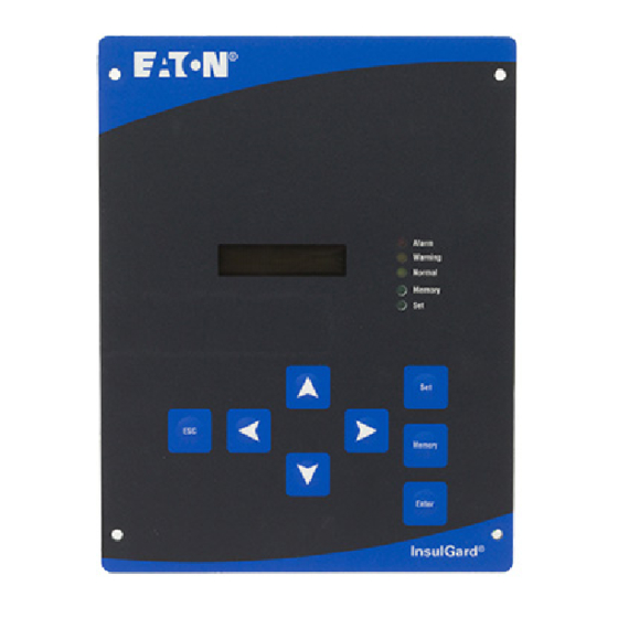
The InsulGard typically comes preconfigured in based on the configuration worksheet received from the customer at the time of order entry (see Appendix 3 – add link). Be sure that the Insulgard device is designated for this particular project and to be connected to this particular set of sensors. Switching InsulGard devices can require significant reprogramming of database software and InsulGard firmware settings and can lead to errors. - Page 5 Sensor Interface Board Figure 1-2. a, b – front and back view of Door mount InsulGard, c, d - front and back view of IG installed on a switchgear cabinet door. For a panel mount InsulGard, the Sensor Interface Board is installed on the panel under the Monitor. For sensor connections, it is necessary to temporarily remove the Monitor from the panel.
- Page 6 There is no outlet for 230VAC application. Fuse inside InsulGard for 115VAC application:Time-Lag 200mA, 250VAC, 5X20mm type 5ST by BEL Fuse Inc., Catalog # 5ST 200. Fuse inside InsulGard for 230VAC application:Time-Lag 100mA, 250VAC, 5X20mm type 5ST by BEL Fuse Inc., Catalog # 5ST 100.
- Page 7 InsulGard System Installation and Start Up Guideline A door mount InsulGard has the same wiring diagram as a panel mount, but without Din-Rail terminals. The power supply voltage is connected straight to the power input of the unit. Door mount InsulGard installed on switchgear compartment door usually has internal temperature and humidity sensors and doesn’t need external sensors.
- Page 8 Eaton at the time of order entry. Settings can also be verified in InsulGard software: → section "Unit Settings" → "Settings for Channel".NOTE: It is important that the coupling capacitor installed on phase A is connected to Channel #1 to obtain phase reference for the InsulGard hardware and firmware.
- Page 9 11) AC power connection and connection to relays, to RS485 and 4-20mA interfaces Use green plugs on the right side of the InsulGard (Figure 1-6 and 1-8). The green plugs can be wired when the InsulGard is not installed on its panel yet.
-
Page 10: Installation Of The Insulgard Sensors
Monitored object and InsulGard must be de-energized. The best way to de-energize InsulGard is to de-energize the incoming power supply line. On a panel mount InsulGard open the fuse located on the DIN-Rail. All sensors have default cable length of 65’ (20m). Custom lengths may be specified at the time of order entry. - Page 11 InsulGard System Installation and Start Up Guideline IPDS - Integrated Partial Discharge Sensors IPDS sensors are 80pF coupling capacitors (CC) with voltage ratings from 5kV to 38kV and special protection PCB board built in. For sensor installation: a) Sensor must be reliably grounded.
- Page 12 Primary CT secondary winding. CTF is used if there is no metering CT in feeder termination compartment and corresponding metering CT is too far from the InsulGard. Install CTF around a feeder cable of any phase in a motor feeder termination enclosure. It must be installed over the shielded part of the feeder cable with cable shield grounding wire coming through the CT.
-
Page 13: Circuits Integrity Test
1.3 Circuits integrity test 1) Check InsulGard Power Supply Voltage a) The voltage between Line and Neutral contacts of the Insulgard power input must be 115 or 230 VAC +/- 10% in accordance with voltage on InsulGard label. b) The voltage between Neutral and Ground contacts of the Insulgard power input must be near zero. -
Page 14: Insulgard System Installation For A Motor
1.4. InsulGard system installation for a motor 1) Typical Insulgard system for a motor A typical InsulGard for a motor is usually installed on a panel and in a Nema-4X enclosure. Examples of installation shown below: Note: If a conduit is installed on top of the enclosure (b), be sure to use appropriate seals to prevent water from entering. - Page 15 InsulGard System Installation and Start Up Guideline Motor terminal box Motor Load (CT) sensor 2-wires cable Motor to InsulGard. meetering A phase B phase C phase IPDS IPDS IPDS 3 coax. cables to InsulGard Channels 1- 3 Temperature sensor Two 3-wires...
- Page 16 InsulGard System Installation and Start Up Guideline 2) Diagram of the main required connections to Insulgard Motor terminal box RTD terminal box InsulGard Enclosure NEMA 4 3 coax cables from coupling 1 coax cable per RTD capacitors from RTD PD sensor(s)
- Page 17 If the existing RTD termination box is not large enough, an auxiliary box will need to be installed next to it, to house the RTD Module and wired in appropriately. e) Run six coax cables to the InsulGard (12 if 2 modules are supplied for 12 RTDs) and connect to the Sensor Interface board.
-
Page 18: Insulgard System Installation For A Switchgear Line
1.5. InsulGard system installation for a switchgear line A Door mount InsulGard and two types of PD sensors (IPDS and RFCT) are typically used on switchgear lines. Door mount InsulGard is usually installed on a switchgear compartment door. See door cut out dimension for IG installation in Appendix 4. -
Page 19: Start Up
StartUp Procedure Guideline does not replace InsulGard and its sensors Manuals. The procedures described below Required Items The following items and set of documentation shipped with InsulGard are required for the functionality tests and start - Set of documentation shipped with the InsulGard(s) and sensors:... - Page 20 4. Device setting may be modified by third party if it was an indirect shipment. Or devices assigned for different projects or for different locations for the same project could be switched. Verify that the proper Insulgard device has been installed. Commonly there is a sticker on an InsulGard face plate with name of the object and device address.
-
Page 21: Verifying/Correcting Configuration
Set Correct Date and Time The time and date on the InsulGard was set in Minneapolis, Minnesota. Local time and date must be entered. Also if a device has spent too much time on a shelf, backup clock battery can be discharged and date/time corrupted: 1. - Page 22 6. Send setting to the device. Calibration/Verification procedure Use GKI-2 pulse generator by Eaton to inject pulse in common mode between the HV conductor and ground using cable with alligator clips. If different pulse generator used, set the generator pulse parameters: Pulse Magnitude ~10 Volt, Pulse Width –...
- Page 23 Figure 2-1 Calibration Verification steps 1. Switch the generator ON and run “Single Measurement” from Communications tab of the InsulGard software. A measurement time is proportional to the number of active channels and will take approximately 1.5 minutes for maximum 15 active channels.
-
Page 24: Baseline Measurement On Energized Object
2.5 Baseline Measurement on Energized Object At this point all signal cables are connected and the InsulGard is powered up, the equipment energized and running and the software is installed on the PC. Data base configuration is verified and corresponds to the application. - Page 25 Potential Transformer or from any source with known phase shift to HV system voltage – see Appendix 7 of InsulGard User Manuals. Reference signal must not exceed 5VAC RMS – use appropriate divider to bring reference signal into preferable range of 0.1-1 VAC. This operation should be performed one time considering that InsulGard power and system voltage connections have not been changed during monitoring.
-
Page 26: Load Current Channel Calibration
8. Return H%/Ref switch into H% position. 9. After finishing with phase shift measurement and exiting setting mode in InsulGard go to Unit Settings Tab in the software and type final phase shift angle value in Phase Reference Shift box or go to Communications Tab in the software and Get Settings from Device to synchronize settings in the monitor and software. - Page 27 PD diagnostics purpose. Multiply CK coefficient by number of feeders in such case. 10. After exiting setting mode in InsulGard go to Communications Tab in the software and Get Settings from Device to synchronize settings in the monitor and software. Click Update Data base with Device settings when CK discrepancy will be displayed.
-
Page 28: Base Line Measurements
7. Go to the Unit Settings screen and change the Data Storage Mode from "Test" to "Normal". 8. If load sensor on a rotating machine is functioning properly check the box next to Load% to suspend InsulGard measurements while machine is out of operation. -
Page 29: Appendix 1. Pd System Installation Checklist
Verify that it is the system designated for the object. Temporal Object name: label on the front panel of an InsulGard shows the object Object nameplate information: name. The serial number on the InsulGard label should Insulgard serial number coincide with InsulGard serial number in database software for this object. - Page 30 1. Base line measurements performed in Test Mode – 2. Data downloaded into database – 3. Data analyzed, necessary changes to the settings have been made - 4. InsulGard set in Normal Saving Mode and left for monitoring Customer training 1. Install software to the customer computer 2.
-
Page 31: Appendix 2. Installation / Commissioning Report
InsulGard System Installation and Start Up Guideline Appendix 2. Installation / Commissioning Report (To fill out below tables you can copy this appendix to word file.) Write down name of the object and InsulGard s/n. Table 1 Check power voltage for the monitor. - Page 32 InsulGard System Installation and Start Up Guideline Table 4. PD sensors configuration for Rotating Machines. After terminating coax cables from the sensors to the InsulGard Sensor Interface Board check resistance at PD signal termination strip between central wire and shield of PD sensors coax cables:...
-
Page 33: Appendix 3. Pd Sensors Designation In Database
RTD - RTD-6 PD sensor (old design) Typically the InsulGard monitor comes preconfigured in accordance with available information on the application and the configuration worksheet filled out at the time of order entry (see example below of PD sensor location on a switchgear line). - Page 34 InsulGard System Installation and Start Up Guideline Insulgard Settings for Channels in database have same designations of the sensors as in the above table. If the sensors positions were changed at installation, the sensor designation in the database must be changed...
-
Page 35: Appendix 4. Door Cutout Dimensions For Door Mount Insulgard
InsulGard System Installation and Start Up Guideline Appendix 4. Door cutout dimensions for Door mount InsulGard Blue color shows InsulGard front panel dimension.
Need help?
Do you have a question about the InsulGard and is the answer not in the manual?
Questions and answers