Table of Contents
Advertisement
Before using your 4PK-2.4GHz system, read this manual carefully in order to use
Application, Export, and Modification
1. This product may be used for models only. It is not intended for use in any application
other than the control of models for hobby and recreational purposes.
2. Exportation precautions:
(a) When this product is exported from the country of manufacture, its use is to be ap-
proved by the laws governing the country of destination for devices that emit radio fre-
quencies. If this product is then re-exported to other countries, it may be subject to re-
strictions on such export. Prior approval of the appropriate goverment authorities may
be required. If you have purchased this product from an exporter outside your country,
and not the authorized Futaba distributor in your country, please contact the seller im-
mediately to determine if such export regulations have been met.
(b) Use of this product with other than models may be restricted by Export and Trade
Control Regulations, and an application for export approval must be submitted.
3. Modification, adjustment, and replacement of parts: Futaba is not responsible for un-
authorized modification, adjustment, and replacement of parts on this product. Any such
changes may void the warranty.
Compliance Information Statement (for U.S.A.)
This device, trade name Futaba Corporation of America, model number R604FS, com-
plies with part 15 of the FCC Rules. Operation is subject to the following two conditions:
(1) This device may not cause harmful interference.
(2) This device must accept any interference received, including interference that may
cause undesired operation.
The responsible party of this device compliance is:
Futaba Service Center
3002 N Apollo Drive Suite 1, Champaign, IL 61822 U.S.A.
TEL (217)398-8970 or E-mail: support@futaba-rc.com (Support)
TEL (217)398-0007 or E-mail: service@futaba-rc.com (Service)
2
Thank you for purchasing a Futaba 4PK-2.4GHz system.
your R/C set safely.
After reading this manual, store it in a safe place.
Advertisement
Table of Contents

Related Manuals for FUTABA 4PK-2.4GHZ


Summary of Contents for FUTABA 4PK-2.4GHZ
- Page 1 Thank you for purchasing a Futaba 4PK-2.4GHz system. Before using your 4PK-2.4GHz system, read this manual carefully in order to use your R/C set safely. After reading this manual, store it in a safe place. Application, Export, and Modification 1. This product may be used for models only. It is not intended for use in any application other than the control of models for hobby and recreational purposes.
- Page 2 You may contact your local recycling center for information on where to return the spent battery. Please call 1-800-8-BATTERY for information on Ni-Cd / Mi-MH bat- tery recycling in your area. Futaba Corporation of America's involvement in this pro- gram is part of its commitment to protecting our environment and conserving natural resources.
-
Page 3: Table Of Contents
Table Of Contents For Your Safety As Well As That Of Others ......8 Explanation of Symbols ..............8 2.4GHz System Precautions ............8 High Speed Mode Precautions .............8 Operation Precautions ..............9 Ni-MH/Ni-Cd Battery Handling Precautions ......10 Storage and Disposal Precautions ..........11 Other Precautions ...............11 Before Using ..............12 Features ..................12 Set Contents ................14... - Page 4 Initial Set-Up ...............35 For Your Safty Preparations (Transmitter) ............35 As Well As Function Map ..............38 That Of Others Menu Selection ................38 Function Menu Screen .............38 Before Menu Screen ................39 Using Custom Menu ................40 Direct Selection ................42 List of functions by menu type ..........44 Functions List ................45 Installation Functions ................46...
- Page 5 Model memory reset Menu Type Select ..............103 Function menu type selection ESC Link Function "MCLNK" ..........104 Special function, Futaba ESC (MC850C, MC601C, MC401CR) System Functions "SYSTM" ............108 Battery type setting Liquid crystal screen backlighting display mode setup Setting of ON time...
- Page 6 Data Transfer "DTTRN" ............112 The T4PK model memory data to another T4PK Adjuster "ADJST" ..............114 For Your Safty Steering wheel and throttle trigger correction As Well As Vibrator Function "VIBRA" ............116 That Of Others Vibrator setting Steerind Dual Rate "D/R" ............117 Steering angle adjustment while running (dual rate) Before ATL Function "ATL"..............118...
-
Page 7: For Your Safety As Well As That Of Others
Under other conditions, the set will not operate, or the specified performance will not be displayed even if it operates. In addition, it may cause servo trouble. Futaba will not be responsible for damage, etc. caused by combination with the products of other companies. -
Page 8: Operation Precautions
Operation Precautions Warning Do not operate outdoors on rainy days, run through puddles of water or use when visibility is limited. Should any type of moisture (water or snow) enter any component of the system, erratic opreation and loss of control may occur. -
Page 9: Ni-Mh/Ni-Cd Battery Handling Precautions
When making adjustments to the model, do so with the engine not running or the motor discon- nected. You may unexpectedly lose control and create a dangerous situation. (Fail safe function) Before running (cruising), check the fail safe function. Check Method; Before starting the engine, check the fail safe function as follows: 1) Turn on the transmitter and receiver power switches. -
Page 10: Storage And Disposal Precautions
Always use only genuine Futaba transmitters, receivers, servos, ESCs (electronic speed con- trols), Ni-MH/Ni-Cd batteries and other optional accessories. Futaba will not be responsible for problems caused by the use of other than Futaba genuine parts. Use the parts speci- fied in the instruction manual and catalog. -
Page 11: Before Using
Before Using Features Frequency channel setting unnecessary: Channel shifting takes place within the 2.4GHz band automatically, this system minimizes the interference from other 2.4GHz systems. Model names can use up to 10 letters, numbers, and symbols, so that logical names may be used. - Page 12 This function assigns functions to 3 switches. The operating direction can also be set. This is a dedicated function which allows setting of the contents of the Link software which makes possible Futaba speed controller (ESC), MC850C, MC601C, MC410CR, etc. variable frequency and other data changes by PC at the T4PK.
-
Page 13: Set Contents
Always use only genuine Futaba transmitters, receivers, servos, ESCs (electronic speed con- trols), Ni-MH(Ni-Cd) batteries and other optional accessories. Futaba will not be responsible for problems caused by the use of other than Futaba genuine parts. Use the parts speci- fied in the instruction manual and catalog. -
Page 14: Transmittert4Pk
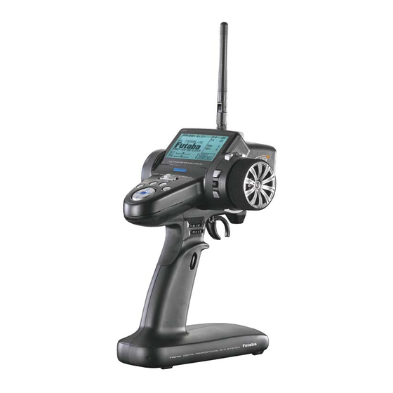
Transmitter T4PK Nomenclature Antenna Push switch 3 (PS3) Digital Dial 3 (DL3) LCD screen Digital Trim1 (DT1) (default steering trim) Power&Display Steering wheel switch Edit buttons Digital Trim 2 (DT2) (default throttle trim) Digital Dial 1(DL1) (default dual rate) Push switch 2 (PS2) Digital Dial 2(DL2) (default ATL) Grip Handle... -
Page 15: Power & Display Switch
Power & Display Switch The power switch and display switch of the T4PK are integrated. In the PWR ON mode, radio waves are transmitted and in the DISP ON mode, model data, settings can be checked without transmitting radio waves. PWR ON Radio waves are being transmitted... -
Page 16: Digital Trim Operation
Digital Trim Operation (Initial settings: DT1: Steering trim, DT2: Throttle trim, DT3: -------) Digital trims can be used in 2 ways: Operating by the lever: Push the lever to the left or right (up or down) Operating by push button switch: Press the push button switch in the desired direction. The current position is displayed on the LCD screen in the bottom three rows of the list. -
Page 17: Mechanical Atl Adjustment
Mechanical ATL Adjustment Make this adjustment when you want to decrease the stroke of the brake (back) side of the throttle trigger for operation feel. Adjustment brake (reverse) stroke. (The screw moves the throttle trigger stopper.) Mechanical ATL adjusting screw Note: Once you have changed the mechanical stroke on the brake side, be sure to adjust the scale of the throttle channel accordingly by using the "Adjuster Function"... -
Page 18: Trigger Slide Adjustment
Trigger slide adjusting screw Ni-MH Battery Replacement The Ni-MH battery is connected by a Futaba J connector so that it can be removed when you will not be using the transmitter for a long time, or when replacing a dead battery with a spare battery. -
Page 19: Charging The Ht5F1700B Battery
To transmitter Ni-Cd battery charging jack When using Futaba CR-2000 The HT5F1700B is 5-cells, so, when charging the HT- 5F1700B battery with Futaba CR-2000 charger, you have to use the RX output side. Charging jack Over current protection The transmitter charging circuit is equipped with an over cur- Cover rent protection circuit (1.7A). -
Page 20: Grip Vibrator
5CELL. (See page 108, for a detailed description of the battery types.) User name display When the (END) button is held down for 1 second or longer at the initial screen, the Futaba logo and user name are displayed for about 2 seconds. -
Page 21: Edit Button Lock And Trim/Dial Lock
Edit button lock and trim/dial lock T4PK setup and operation by edit button (p.15) and digital trim DT1, DT2, and DT3 and dials DL1, DL2, and DL3 can be prohibited. Setting Edit button lock: When the (+) button is pressed for about 1 second at the initial screen, a confirmation beep is generated and the edit button lock display appears on the screen. -
Page 22: Changing Wheel Position And Modifying For Left-Hand Use
Changing wheel position and modifying for left-hand use Changing the wheel position The wheel position can be offset by using the acces- sory APA wheel position offset adapter. (See the page 24 for the modification method.) Modifying for left-hand use The wheel section left and right installation direction can be reversed. - Page 23 Remove the steering wheel unit. Disconnect the steering wheel unit connector. Wheel unit Installing the accessory APA steering wheel offset adapter original screws. The steering wheel unit connector through the adapter. Adapter APA Install the steering wheel unit us- Unit mounting screws ing the 3 mounting screws.
- Page 24 Pull out the wiring as far as possible from between the wheel unit and APA. Stow the surplus pulled out wiring in the transmitter. Stow the surplus wiring here. Install the assembled wheel unit and APA to the transmitter using the screw supplied. The APA mounting screws are in the hook and APA mounting screws bag.
- Page 25 Modifying for left-hand use Remove the wheel section rear cover . serting a coin, etc. into the slot at the bottom of the rear cover. Push in the disconnected connector so that it can be connected at the opposite side. At the opposite side, connect the steering wheel unit connector and Install the steering wheel unit,...
-
Page 26: Installing The Accessory Hook
Installing the accessory Hook A hook can be installed to the T4PK, as required. The hook is in the hook and APA mounting screws bag supplied with the set. Pull up the bottom of the grip rub- ber as shown in the figure. Grip rubber Pull out the grip rubber in the arrow direction. -
Page 27: About Transmitter Antenna And Receiver
About Transmitter Antenna and Receiver About The Transmission Antenna Antenna to the ground. Antenna Moving Range Warning Otherwise, the operating range may become shorter. Never hold only the antenna. Hold the grip handle, otherwise the antenna may be damaged. The antenna position can be changed in the range as shown in figures A and B. However, please do not apply unnecessary force or shock. -
Page 28: How To Link The Transmitter And The Receiver
Receiver Terminology Tactile switch/LED Connectors Antenna :CH4 servo(CH4)/Power connector :CH3 servo(CH3) :Throttle servo(CH2) :Steering servo(CH1) DSC :DSC connector How to link the transmitter and the receiver Each transmitter has an individually assigned, unique ID code. In order to start opera- tion, the receiver must be linked with the ID code of the transmitter to which it is being paired. -
Page 29: Receiver Installation
Under other conditions, the set will not operate, or the specified performance will not be displayed even if it operates. In addition, it may cause trouble of servo and other equipments. Futaba will not be responsible for damage, etc. caused by combination with the products of other companies. -
Page 30: Installation
Installation Receiver and Servo Connections Connect the receiver and servos as shown below. Connect and install the receiver and servos in accordance with "Installation Safety Precautions" on the next page. The figure shown below is an example. The method of connecting the motor controller to the motor and battery depends on the motor controller used. -
Page 31: Installation Safety Precautions
Installation Safety Precautions Warning Receiver (receiver antenna) Do not cut or bundle the receiver antenna wire. Do not bundle the receiver antenna wire together with the motor controller lead wire. Keep the receiver antenna wire at least 1cm away from motor, battery, and other wiring carrying heavy current. Do not use a metal receiver antenna holder on a plate made of metal, carbon, or other conductive material. - Page 32 Warning Connector Connections Be sure the receiver, servo, battery and connectors are fully and firmly connected. If vibration from the model cause a connector to work loose while the model is in operation, you may lose control . Servo Installation When you install the servos, always use the rubber grommets provided in servo hardware bags.
- Page 33 Warning Electronic speed control Install the heat sinks where they will not come in contact with aluminum, carbon fiber or other parts that conduct electricity. If the FET Amp (Electronic speed control) heat sinks touch other materials that conduct electricity a short circuit could occur.
-
Page 34: Initial Set-Up
2.Rx Type Check The T4PK transmitter can use the Futaba 2.4GHZ R603FS/FF. However, there are two types of Futaba 2.4GHz receiver for vehicles: "C1" type and "C2" type. The R603FS and 603FF are "C1" type. The R604FS supplied with the 4PK set as standard is the "C2"... - Page 35 3. Servo Response Mode Check Check that the servo response setting matches the servo be- ing used. When using a digital servo (including BLS Series brushless servo), both HIGH SPEED and NORMAL can be used. When an analog servo is used, HIGH SPEED cannot be used;...
- Page 36 Steering dual rate - Steering dual rate (BT1) check At initial set-up, steering dual rate (D/R) is assigned to DL1 dial, at the grip of the transmitter. Operate the DL1 and check if the D/R value displayed on the screen changes. After checking ST.D/R, set the steering dual rate to 100%.
-
Page 37: Function Map
Function Map Menu Selection The function set-up screen can be easily selected from the function menu displayed on the LCD screen. The function menu can be selected from among the following 4 types to match the level of use. To select the type, use the Menu type select function (page 103). -Level 1 (LEVEL1) : Basic functions only -Level 2 (LEVEL2) : For middle class driver -Big car(BIGCAR) -
Page 38: Menu Screen
Menu Screen The menu screen displays 18 items on 3 rows and 6 lines on one page and displays up to 36 items on 2 pages designated MENU1 and MENU2. A menu screen matched to the When the cursor is in a position without Menu No. -
Page 39: Custom Menu
Custom Menu A menu matched to the purpose (custom menu) can be created by using the menu cus- tomize function. A different menu can be created for each model memory. In addition, custom menus can be copied to other models by using menu copy of the model copy function (page 100). - Page 40 Customizing all functions. In addition to the menu types shown page 38, there is ALL- OFF. It is convenient when customizing all functions. (Opening Screen) Call the menu screen from the initial screen by (JOG) button up, down, life, or right operation. On the MENU1 screen, move the cursor to "*MENU-T"...
-
Page 41: Direct Selection
Direct Selection The Direct Selection allows instant access to the six functions most frequently used. The function set-up screen can be directly and quickly called with the special buttons for each of the eight functions. They can be freely selected by pressing Direct Selection But- ton (DIR) function. - Page 42 Direct Customize With the T4PK, your favorite direct call matched to the purpose can be assigned to the edit buttons by using the direct customize function. Direct call lets you create a different menu for each model memory. Direct call assigned to each edit button can also be copied to other models by using menu copy of the model copy function (page 100).
-
Page 43: List Of Functions By Menu Type
List of functions by menu type Function LEVEL1 LEVEL2 BIGCAR LEVEL3 Function abbreviation (Initial setting) STEXP STSPD THEXP THSPD A.B.S ACCEL START BRAKE IDLUP TIMER LAP-L PMIX1 PMIX2 BOAT SUBTR * M-SEL * M-RES M-COP NAME DIAL SWTCH CH3/4 RXSYS * MENU-T SYSTM DTTRN... -
Page 44: Functions List
Function list Function Page Function Description of function abbreviation P-49 End point adjustment STEXP P-56 Steering curve adjustment STSPD P-61 Steering servo delay THEXP P-57 Throttle curve adjustment THSPD P-63 Throttle servo delay A.B.S P-69 Pumping brake ACCEL P-52 Function which adjusts the rise characteristic from the throttle neutral position START P-66 Throttle preset at start function/ engine cut off by switch... -
Page 45: Functions
Receiver Type / Servo Response Mode "RXSYS" Receiver There are two types of Futaba 2.4GHz receivers for cars depending on the system dif- ferences: C1 type and C2 type. The R603FS and 603FF are C1 type and the R604FS supplied with the 4PK set as standard is C2 type. For the R603FS and 603FF, set RX... -
Page 46: Servo Reverse "Rev
Servo Reverse "REV" (All channel) This function reverses the direction of operation of the servos related to transmitter steering, throttle, and channel 3 operation. However, when the position set by trim or subtrim shifts from the center, the center becomes the opposite side. Calling the setup screen *Calling from menu screen button... -
Page 47: Subtrim "Subtr
Subtrim "SUBTR" (All channel) Use this function to adjust the neutral position of the steering, throttle, channel 3 and channel 4 servos. 90deg *Subtrim adjusts the entire range of the servo in the set direction. Use to adjust the neutral position Calling the setup screen *Calling from menu screen button... -
Page 48: Set-Up
End Point Adjuster "EPA" (All channel) Use this when performing left and right end point adjustments, throttle high side/ brake side operation amount adjustment, channel 3 and channel 4 servo up side/ down side operation amount adjustment during linkage. - Correct the maximum steering angle for left and right steering angles when there is a difference in the turning radius due to the characteristics, etc. - Page 49 Calling the setup screen Setting item (channel and direction) *Calling from menu screen button ST-LFT :Steering (left side) (Opening Screen) ST-RGT :Steering (right side) * b l i n k s a t t h e c u r r e n t Menu screen call TH-FWD :Throttle (foward side) setup item.
- Page 50 Throttle (EPA) adjustment 100% (Preparation) - Before setting the throttle end point adjustment(EPA), set the throttle ATL dial (initial setup: DL2) to the maximum throttle angle position 100%. - Select the setting item "TH-FWD" by (JOG) button up or down operation and make the following adjustments: Throttle (forward side) adjustment Adjust button Pull the throttle trigger fully to the high side and use...
-
Page 51: Throttle Acceleration "Accel
Throttle Acceleration "ACCEL" (Throttle system) The servo will jump to the input position at its maximum possible speed. Unlike expo- nential, which adjusts the whole throttle movement into a curve, throttle acceleration simply "jumps" away from neutral and then leaves the remaining response linear. Operation 100% - Operation near the throt-... - Page 52 Throttle acceleration adjustment Adjust button Adjust with the (+) and (-) but- (Preparation) tons. - Return to the initial value "0" by - Select the setting item "FWRD" by (JOG) button up or down pressing the (+) and (-) buttons operation and make the following adjustments: simultaneously for about 1 sec- ond.
-
Page 53: Fail Safe/Battery Fail Safe Function "F/S
Fail Safe/Battery Fail Safe Function "F/S" (All channel) Fail Safe Mode (F/S) This function moves each servo to a preset position when the receiver cannot receive the signals from the transmitter for some reason. -When "Rx Type"(p.46) is set "FASST-C1" and "Servo Response"(p.46) is "NORMAL", the setting fail safe (F/S) is only throttle (TH). - Page 54 Setup item selection Fail safe mode selection - Select by (JOG) button up or (Preparation) down operation. - Select the channel to be set by (JOG) button operation. F/S mode selection (Mode selection) - Select with the (+) or (-) but- Select the mode by (+) or (-) button.
-
Page 55: Steering Exponential "Stexp
Steering EXP "STEXP" (Steering system) This function is used to change the sensitivity of the steering servo around the neutral position. It has no effect on the maximum servo travel. Racers Tip When the setting is not determined, or the characteristics of the model are unknown, start with 0%. -
Page 56: Steering Operation Curve Adjustment Throttle Exponential "Thexp
Throttle EXP "THEXP" (Throttle system) This function makes the throttle high side and brake side direction servo operation quicker or milder. It has no effect on the servo maximum operation amount. For the high side, selection from among three kinds of curves (EXP/VTR/CRV) is also possible. - Page 57 Adjustment method for EXP curve (Preparation) Curve type Select button - Select with the (+) or (-) but- - With the jog dial, move the blinking cursor up or down to select "FWD- tons. TYP". With the plus (+) or minus (-) buttons, select EXP. - With the jog dial, move the blinking cursor up or down to select "RATE"...
- Page 58 Adjustment method for VTR curve (Preparation) Curve type Select button - Select with the (+) or (-) but- - With jog dial, move the blinking cursor up or down to select "FWD-TYP". tons. Use the plus (+) or minus (-) keys to select "VTR". - With the jog dial, move the blinking cursor up or down to select "RATE"...
-
Page 59: Throttle Curve Adjustment
Adjustment method for VTR curve Curve type Select button (Preparation) - Select with the (+) or (-) but- - Select "CRV" at setup item "FWD-TYP". tons. Point in current setup Setup items A ve r t i c a l c u r s o r l i n e t h a t 1:~5 :Curve points 1~5 shows the point in the current... -
Page 60: Steering Speed "Stspd
Steering Speed "STSPD" (Steering system) Quick steering operation will cause momentary understeering, loss of speed, or spinning. This function is effective in such cases. Spin Smooth cornering Understeering Without "STSPD" With "STSPD" Operation - This function limits the maximum speed of the steering servo. (Delay function) - T he st e er i ng sp e e d when the steering wheel is operated (TURN direction) and returned... - Page 61 Steering Speed adjustment Setup item selection (Preparation) - Select by (JOG) button up or - Select the setting item "TURN" by (JOG) button up or down down operation. operation, and make the following adjustments: "TURN" direction adjustment Use the (+) or (-) buttons to adjust the delay amount.
-
Page 62: Throttle Speed "Thspd
Throttle Speed "THSPD" (Throttle system) Sudden throttle trigger operation on a slippery road only causes the wheels to spin and the ve- With "THSPD": Quick start without skidding hicle cannot accelerate smoothly. Setting the throttle speed function reduces wasteful battery consumption while at the same time permitting smooth, enjoyable operation. - Page 63 Adjustment method for 1 SPEED (Preparation) Speed type Select button - Select with the (+) or (-) but- - Select the setting item "MODE" by (JOG) button up or down tons. operation. Press the (+) or (-) button and select "1 SPEED". Setting item MODE :Speed type selection When a value of 99 or less is...
- Page 64 Adjustment method for 3 SPEED Speed type Select button (Preparation) - Select with the (+) or (-) but- - Select the setting item "MODE" by (JOG) button up or down tons. operation. Press the (+) or (-) button and select "3 SPEED". When a value of 99 or less is set at either LOW or HIGH, the dis- Setting item...
-
Page 65: Start Function, Engine Cut "Start
Start Function, Engine Cut "START" (Throttle system) When the throttle trigger is set to full throttle simultaneously with starting when the track is slippery, the car wheels will spin and the car will not accelerate smoothly. When the Start function is activated, merely operating the throttle trigger slowly causes the throttle servo to automatically switch from the set throttle position to a preset point so that the tires do not lose their grip and the car accelerates smoothly. - Page 66 Start function adjustment Setup item selection (Preparation) - Select by (JOG) button up or - Select the setting item "MODE" by (JOG) button up or down down operation. operation. Press the (+) or (-) button and select "AT&SW". - Select setup item "TG.P" and make the following adjustments. When the trigger is moved to the HI side, and the trigger position Setup items...
- Page 67 Engine Cut function adjustment Setup item selection (Preparation) - Select by (JOG) button up or - Use the function select switch to select the switch. down operation. Setup items PRST : Preset position MODE : Function selection Setup item selection - Select by (JOG) button up or down operation.
-
Page 68: A.b.s. Function "A.b.s
A.B.S. Function "A.B.S" (Throttle system) When the brakes are applied while cornering with a 4 Wheel Drive or other type of vehicle, understeer may occur. The gen- eration of understeer can be eliminated and corners can be smoothly cleared by using this function. Operation Without A.B.S. - Page 69 - ABP : Amount of brake return A.B.S Sets the rate at which the ser- DTY (duty): X and Y ratio Y: (Brake return time) vo returns versus trigger oper- X: (Brake application time) ation for brake release. When set to 0%, the ABS function TGP (Trigger point) (Amount of is not performed.
- Page 70 A.B.S function adjustment Setup item selection (Function ON/OFF) - Select by (JOG) button up, Select the setting item "MODE" by (JOG) button up, down, down, left or right operation. left or right operation. Set the function to the active state by Adjustment buttons pressing the (+) or (-) button.
- Page 71 (Cycle duty ratio setup) Select setting item "DTY" by (JOG) button up, down, left Duty ratio (DTY) or right operation. Use the -3 ~ 0 ~ +3 Y: (Brake return time Initial value; 0 (+) or (-) button to adjust the duty ratio.
- Page 72 Fail Safe Unit When the T4PK is used with the Futaba fail safe unit (FSU-1), it will operate as de- scribed below. - When the FSU-1 is connected to the throttle channel, and the A.B.S. function has been activated, the FSU-1 LED will flash each time the servo operates. The reason for this is that the FSU-1 responds to sudden data changes caused by A.B.S.
-
Page 73: Brake Mixing "Brake
Brake Mixing "BRAKE" (Throttle, 3rd channel system) This function is used when the front and rear brakes must be adjusted independently such as a 1/5 scale GP car. This mixing uses the 2nd CH for the rear brakes and the 3rd or 4th CH for the front brakes;... - Page 74 Calling the setup screen *Calling from menu screen button (Opening Screen) * b l i n k s a t t h e c u r r e n t Menu screen call setup item. button MENU 1 * When set to BRK-MODE "ACT" MENU1/2 selection the brake mixing function is ex- button...
- Page 75 Brake mixing adjustment Setup item selection (Function ON/OFF) - Select by (JOG) button up, down, left or right operation. Select the setting items "BRK-MODE(CH3)" or "(CH4)" by Adjustment buttons (JOG) button up, down, left or right operation. Set the func- - Use the (+) and (-) buttons to tion to the active state by pressing the (+) or (-) button.
- Page 76 (Steering mixing) Use this function when you want to weaken the front brakes when steering was operated. Select the setting item "STM- LFT" or "STM-RGT" by (JOG) button up, down, left, or right Brake rate (STM-LFT/STM-RGT) 0 ~ 100 operation. Use the (+) or (-) Initial value:100 button to adjust the brake amount.
-
Page 77: Boat Mode "Boat
Boat Mode "BOAT" (Steering, Throttle, system) Shutting off brake side operation When brake side operation is unnecessary with a boat, etc., it can be shut off. Tilt mixing Tilt mixing uses an outboard engine and applies bidirectional mixing from rudder (steer- ing) to channel 3 and from channel 3 to rudder so that with a boat rudder operation and tilt mixing operation can be performed by 2 servos. - Page 78 Tilt mixing adjustment (Preparation) Adjustment buttons - Use the (+) and (-) buttons to - Use the function select dial function to select the 3rd channel make adjustments. operation dial. (page 88) - Return to the initial value by pressing the (+) and (-) buttons simultaneously (approx.
-
Page 79: Throttle Mode "Thmod
Neutral brake, which applies the brakes at the throttle trigger neutral position, can be set. However, for Futaba speed controller (ESC) MC850C, MC601C, MC401CR, etc, consid- ering safety, when the neutral position is not confirmed, the set will not enter the opera- tion mode to prevent the motor from rotating instantly when the power was turned on. -
Page 80: Neutral Brake Function
Neutral Brake function adjustment (Preparation) - Use the function select switch function to select the switch. (page 86) (Neutral brake rate) Select the setting item "NT-BRK" by (JOG) button up or down operation. Use the (+) and (-) buttons to set the neutral brake rate. -
Page 81: Idle-Up "Idlup
Idle-Up "IDLUP" (Throttle system) This function is a function select switch function. The idle-up function ON/OFF switch must be set. (Page 86) It is used to improve engine starting performance by raising the idling speed when the engine of a gasoline car (boat) is started. This function is also effective when you want to prevent braking when the power was turned off during running due to the effect of gear ratio setting and the motor used with a motor car. -
Page 82: Programmable Mixes 1/2 "Pmix1,2
Programmable Mixes 1, 2 "PMIX1, 2" (All channels) These functions allow you to apply mixing between the steering, throttle, channel 3 and channel 4. Two programmable mixing systems can be used. The programmable mixing 1 and pro- grammable mixing 2 set-up screens are independent. Additional Functions -When the steering or throttle channel is the master channel (channel that applies mix- ing), trim data can be added. - Page 83 Program mixing adjustment Setup item selection (Preparation) - Select by (JOG) button up, - Use the function select switch function (page 86) to select the down, left or right operation. switch. (as desired) Switch PRG MIX1 : Program mixing 1 (Mixing function ON/OFF) PRG MIX2 : Program mixing 2 Select the setting item "MODE"...
- Page 84 Trim mode (TRM) (Trim mode setup) OFF, ON Select setup item "TRM" by (JOG) button up, down, left, or Initial value: OFF right operation, and use the (+) or (-) button to select the mixing mode. "OFF" :Trim is added. "ON"...
-
Page 85: Function Select Switch "Swtch
Function Select Switch "SWTCH" This function allows selection of the function to be performed by the switches (PS1/PS2/PS3) and setting of the direction, etc. of operation. -The table to the right shows the functions that can be assigned to each push switch. -PS1 and PS2 can be made alternate operation (ON/OFF switched each time SW pressed). - Page 86 Settable functions (SW1/SW2/SW3) Abbreviation used on setup screen Function name, etc PRESET Start function /Preset (Engine cut) NT-BRAKE Neutral brake function ON/OFF A.B.S.CH2 A.B.S function (2CH)ON/OFF A.B.S.CH3,CH4 A.B.S function (3CH,4CH)ON/OFF 2ND COND 2nd condition function ON/OFF IDLE-UP Idle up function ON/OFF PROG MIX1 Program mixing1 function ON/OFF PROG MIX2...
-
Page 87: Function Select Dial "Dial
Function Select Dial "DIAL" This function allows selection of the function performed by the digital dial (DL1/DL2/ DL3) and digital trimmers (DT1/DT2/DT3), step amount adjustment, and operating di- rection reversal. - The table below lists the functions that can be assigned to each dial and digital trimmer. The assigned function is also displayed on the opening screen together with the current adjust- ment value. - Page 88 Relationship between set value Settable functions (DL1/DL2/DL3, DT1/DT2/DT3) and step amount Abbrevia- Abbreviation tion used on displayed on Function name, etc (Setting range: 1, 2, 5, 10, 20, 30, 40, setup screen opening screen 50, 100, 2PS) (D/R) Dual rate function -Steering trim/throttle trim (ATL) ATL function...
-
Page 89: Timer Function "Timer
Timer Function "TIMER" Use the timer by selecting one of the four timers UP TIMER, DOWN TIMER, LAP TIMER and LAP NAVIGATE timer. UP TIMER function - The UP TIMER can be used to count the time between start and stop, etc. - The timer repeatedly starts and stops each time the switch is operated and accumulates the time between each start and stop. - Page 90 LAP TIMER LAP TIMER function - The LAP TIMER can memorize each lap time of each switch operation. (98 laps) - The race time can be set. Switch operation after the set time by alarm has elapsed automatically stops the timer.. Prealarm can also be set.
- Page 91 Calling the setup screen button *Calling from menu screen button (Opening Screen) * blinks at the current setup item. * b l i n k s a t t h e c u r r e n t Menu screen call setup item.
- Page 92 Using the up timer Adjustment buttons (Preparation) - Use the (+) and (-) buttons to Select the setting item "TYPE" by (JOG) button up or down make adjustments. operation. Press the (+) or (-) button and select "UP TIMER". - Press the (+) and (-) buttons simultaneously (approx.
- Page 93 Using the fuel down timer Adjustment buttons (Preparation) - Use the (+) and (-) buttons to Select the setting item "TYPE" by (JOG) button up or down make adjustments. operation. Press the (+) or (-) button and select "FUEL DOWN - Press the (+) and (-) buttons simultaneously (approx.
- Page 94 Using the Lap timer timer Adjustment buttons (Preparation) - Use the (+) and (-) buttons to Select the setting item "TYPE" by (JOG) button up or down make adjustments. operation. Press the (+) or (-) button and select "LAP MEMO- - Press the (+) and (-) buttons simultaneously (approx.
- Page 95 Using the navigate timer (Preparation) Adjustment buttons - Use the (+) and (-) buttons to Select the setting item "TYPE" by (JOG) button up or down make adjustments. operation. Press the (+) or (-) button and select "NAVIGATE". - Press the (+) and (-) buttons simultaneously (approx.
-
Page 96: Lap List "Lap-L
Lap List "LAP-L" Call LAP-LIST when checking the lap memory data (each lap time) memorized by lap timer (page 90, 95 ) operation. - After the lap timer is started, the lap time is sequentially memorized at each switch op- eration. -
Page 97: Model Select "M-Sel
Model Selection "M-SEL" Forty model data (model data for 40 R/C cars) can be saved in the 4PK transmitter and used when the relevant model data is called. Calling the setup screen *Calling from menu screen Select the model # by (JOG) button (Opening Screen) Menu screen call button... -
Page 98: Model Name "Name
(JOG) button is pressed, the model name or user Model name :MODEL-M (#) name is initialized to the factory setting. User name :FUTABA-4PK When ending setting, return to the initial screen by pressing the (END) button twice (for function menu screen, press the (END) button once). -
Page 99: Model Copy "M-Cop
Model Copy "M-COP" The contents of the model memory can be copied to another model memory. Single mode (SINGLE) and group mode (GROUP) Single mode copies the data to another model in model units. Group mode groups M1~M10, M11~M20, M21~M30, and M31~M40 into individual groups and copies the data from group to group. - Page 100 "SINGLE" mode "GROUP" mode "MENU COPY" mode "SW/DIAL COPY" mode Model copying (Preparation) Setup item selection Select setting item "MODE" by (JOG) button up or down op- - Select by (JOG) button up or down operation. eration and select the copy mode from "SINGLE", "GROUP”, "MENU COPY", and "SW/DIAL COPY"...
-
Page 101: Model Reset "M-Res
Model Reset "M-RES" This function resets the contents of the currently called model memory. The reset method can be selected from among the 3 types described below. These resets do not initialize the adjuster function (ADJST), system function (SYSTM), lap reset (LAP-L), user name (NAME), and receiver type (FASST-C1/FASST-C2) , servo re- sponse selection function (RXSYS). -
Page 102: Menu Type Select
Menu Type Selection "MENU-T" The function selection menu matched to the level of use can be selected from among the 4 types shown below. (The menu type can be set for each model.) LEVEL1 LEVEL2 BIGCAR LEVEL3 ALLOFF Caution when lowering the level The set value of the functions removed from the menu when the level was lowered re- mains effective thereafter. -
Page 103: Esc Link Function "Mclnk
This is a special function which lets you set the contents of the Link software which per- forms Futaba speed controller (ESC), MC850C, MC601C, MC401CR, etc. variable frequen- cy and other data changes by PC at the T4PK transmitter. However, the following MC401CR settings cannot be used with the T4PK MC link function. - Page 104 Using the ESC Link function When "MC-LINK" menu is selected when the trans- (Preparation) mitter power switch is at the transmit side (POWER -Connect the T4PK and ESC in accordance with the connec- ON) the message shown tion diagram shown on page 104. below prompting you to set the switch to the display -Connect the battery to ESC.
- Page 105 (Initialization) Write the factory set ESC setting data to the connected ESC and T4PK. -Select the setting item "MODE" by (JOG) button up or down operation, and select "DEFAULT(MC&TX)" by (+) or (-) button. -Select the setting item "EXEC" by (JOG) button up or down operation, and press the (+) and (-) buttons simultane- ously for 1 second or longer.
- Page 106 LBP-(LOW BATTERY VOLT) 2.5V~6V DBA-(DEAD BAND) ±2μs~±50μs Same as Link software Low Bat Protection Same as Link software Dead Band. This setting cuts off the output to the motor when the This sets the range (neutral point range) over which running battery voltage drops to the set voltage to the ESC does not respond to transmitter throttle op- prevent the receiver from stopping operation when...
-
Page 107: System Functions "Systm
Therefore, always set the battery type matched to the power source used. Especially, when using a Futaba rechargeable type battery, always set the battery type to "NI-MH 5-CELL". If the T4PK is used at "DRY 4-CELL" set- ting, the time from low battery alarm to stopping of the system will become ex- tremely short. - Page 108 - Press the (+) and (-) buttons operation, and select the mode by pressing the (+) or (-) button. simultaneously (approx. 1 sec) "NIMH 5CELL" :Futaba 5-cells rechargeable battery to return to the initial screen. "DRY 4CELL" :Dry cell battery (alkaline battery recommended) 4 batteries...
- Page 109 Initial screen mode (DISP-MODE) mode. Futaba, TIMER,SRV-VIEW, USR-NAME, TRM/DIAL "Futaba" :"Futaba" logo is displayed on the initial screen. "TIMER" :Timer screen is displayed on the initial screen. "SRV-VIEW" :Servo operation graph is displayed on the initial screen. "USR-NAME" :User name "TRM/DIAL"...
- Page 110 About second condition function (2ND COND) Two kinds of data can be set in one model for specific functions only. For example, two kinds of data such as steering D/R set to 90% at normal condition and steering D/R set to 80% at second condition.
-
Page 111: Data Transfer "Dttrn
Data Transfer "DTTRN" This function copies the T4PK model memory data to another T4PK. Connect the com- munication port of both T4PK with the optional DSC cord. Use with this function with the T4PK power switch at the display side. Communication port (interior left side) DSC cord for T4PK (option) - Page 112 Setup item selection (Select the setting item ) - Select by (JOG) button up or "MODE" by (JOG) button up or down operation, and select down operation. the transfer side and receive Mode change button - Use the (+) and (-) buttons to side by (+) or (-) button.
-
Page 113: Adjuster "Adjst
Adjuster "ADJST" Steering and throttle correction can be applied. Use this function when a mechanical off- set has occurred for some reason. Calling the setup screen button *Calling from menu screen * b l i n k s a t t h e c u r r e n t (Opening Screen) setup item. - Page 114 Internal checks are performed automatically and when each adjustment point is in a fixed range, correction is performed and "SUCCESSFUL!" (figure at the right) is displayed. If an adjustment point is not within a fixed range, an error is displayed (figure at the right) and the correction data is not updated.
-
Page 115: Vibrator Function "Vibra
Vibrator Function "VIBRA" The vibrator built into the grip can be activated at lap navigation navigate alarm, each racing timer time up, powering ON, push sw on/off and low battery alarm. The vibrator operation pattern can be selected from among 7 types Setup items TIMER TIME-UP TIMER TIME-UP... -
Page 116: Vibrator Setting Steerind Dual Rate "D/R
Steering Dual Rate/Second Dual Rate "D/R" (Steering system) The steering left and right servo travels are adjusted simultaneously. When you want to increase the servo travel, adjust the + side. When you want to decrease the servo travel, adjust the – side. This setting is linked to transmitter grip dial DL1. When DL1 is as- signed another function, dual rate can be adjusted with this screen. -
Page 117: Atl Function "Atl
Throttle ATL Function "ATL" (Throttle system) This function decreases the set value when the braking effect is strong and increases the set value when the braking effect is weak. This function is linked to transmitter grip dial DL2. When DL2 is assigned another function, this function can be set with this screen. -
Page 118: Channel 3/4 Position "Ch3","Ch4
Channel 3/4 position "CH3","CH4" (3rd or 4th channel system) The channel 3/4 servo position can be set from the transmitter. When CH3 is assigned to a dial by the dial function (p.88), this setting is linked to that dial. When CH3/4 is not assigned to a dial, it can be set with this screen. When CH3/4 is assigned to a switch by the switch function (p.86), you cannot adjust the CH3/4 via the screen. -
Page 119: Servo View "Servo
Servo View "SERVO" Servo operation of each channel can be checked. Operation of the steering angle adjust- ment, when a mixing function was set, etc. can be easily checked. The servo view can also be displayed on the initial screen by using the system function (See page 108). The neutral position of the throttle channel varies depending on the modes defined by the "THR-MODE". -
Page 120: Reference
Under other conditions, the set will not operate, or the specified performance will not be displayed even if it operates. In addition, it may cause servo trouble. Futaba will not be responsible for damage, etc. caused by combination with the products of other companies. -
Page 121: Optional Parts
Optional Parts The following parts are available as 4PK options. Purchase them to match your applica- tion. For other optional parts, refer to our catalog. Transmitter Ni-MH Battery When purchasing a transmitter Ni-MH battery as a spare, etc., use the following: Part name NT5F1700B (6V/1700mAh) Please do not use the transmitter's battery, HT5F1700B, as the receiver's battery. - Page 122 DSC cord When the T4PK transmitter and R604FS or R603FS/FF receiver are connected with the DSC cord, the servos can be operated without emitting radio waves. (DSC function) Part name DSC cord for T4PK Connection Communication port (interior left side) DSC cord for T4PK (option) Cover To receiver battery...
-
Page 123: Warning Displays
Tone will sound (9 times), then repeat. Warning When a backup error is generated, immediately stop using the system and request repair from the Futaba Service Center. If you continue to use the system, the transmitter may malfunction and cause loss of control Low Battery Alarm If the transmitter battery voltage drops to 4.9V(when using dry cell battery: 4.1V) or... - Page 124 High voltage alarm If a battery exceeding 8V is used with the T4PK, an audible alarm will sound and "HIGH VOLTAGE" will be displayed on the LCD screen. Immediately remove the battery because it may cause the T4PK to malfunction. LCD screen: Audible alarm: Tone sounds (7 times) and stops (repeated)
-
Page 125: When Requesting Repair (For U.s.a.)
Read the Warranty card. - When requesting warranty service, send the card or some type of dated proof purchase. FUTABA CORPORATION Makuhari Techno Garden Bldg., B6F 1-3 Nakase, Mihama-ku, Chiba 261-8555, Japan Phone: (043) 296-5119 Facsimile: (043) 296-5124 ©FUTABA CORPORATION 2008, 04...
Need help?
Do you have a question about the 4PK-2.4GHZ and is the answer not in the manual?
Questions and answers