Table of Contents
Advertisement
Quick Links
DE
EN
5 operation combined machine
Bedienungsanleitung und
Sicherheitshinweise lesen
und beachten!
Read the operation manual
carefully before first use!
Bedienungsanleitung
User Manual
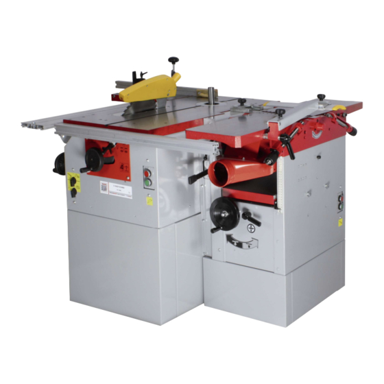
K5 260 L
5-fach Kombination
Ausgabe/Edition: 2012 – Revision 00 – DE/EN
5-fach Kombination
5 operation combined machine
Technische Änderungen
sowie Druck- und
Satzfehler vorbehalten!
Technical data subject to
changes, errors excepted!
Advertisement
Table of Contents

Related Manuals for HOLZMANN MASCHINEN K5 260 L


Summary of Contents for HOLZMANN MASCHINEN K5 260 L
- Page 1 Bedienungsanleitung 5-fach Kombination User Manual 5 operation combined machine K5 260 L 5-fach Kombination 5 operation combined machine Bedienungsanleitung und Technische Änderungen Sicherheitshinweise lesen sowie Druck- und und beachten! Satzfehler vorbehalten! Read the operation manual Technical data subject to carefully before first use! changes, errors excepted! Ausgabe/Edition: 2012 –...
-
Page 2: Use Of The Machine
Foreword Foreword Foreword Foreword These instructions have been created by the device manufacturer and are an integral part of the machine delivery. They contain basic information for qualified operating staff and describe the environment and manners of the machine use for which it has been designed, and also contain any information necessary for the correct and safe operation. -
Page 3: Working Environment
The machine is designed for operation performed by one worker only. The machine may not be handled by children and youngsters in any ma The machine may not be handled by children and youngsters in any manner. The machine may not be handled by children and youngsters in any ma The machine may not be handled by children and youngsters in any ma nner. - Page 4 Planning width 260 mm Table length 1090 mm Cutterblock diameter 75 mm Knives quantity 3 Stk. Thicknesser Table size 600 x 245 mm Planning width 245 mm Cutting height min. / max. 5 / 195 mm Feed rate 8 m/min Motor 1,5 kW / 230 V / 50 Hz or 400 V Circular saw...
-
Page 5: Safety Instructions
influencing actual levels of workers‘ exposure include the properties of the working area, other sources of noise etc., e.g. the number of machines and the other neighbouring procedures. Also the highest permissible levels of exposure may vary in different countries. This information should help the machine user to evaluate the risk and the risk rate in a better manner. - Page 6 circumstances. In the case that you are not going to work on the machine, turn off the machine by the switch and disconnect the plug from the supply socket. Before cleaning the machine, switch off the machine and disconnect the plug of the machine.
- Page 7 hair properly to avoid catching by moving part. Wear suitable tight cloth, shoes recommended or prescribed by labour-safety regulations of all countries. Wear safety outfit (goggles, apron, safety shoes, hearing protection etc.). In the case of any obstacles above your head – in the working area - wear a helmet.
-
Page 8: Safety Regulations For Maintenance
While handling parts above your possibilities, ask for helps from a qualified person. It is not recommended to work on the machine during a storm. Safety regulations for maintenance Safety regulations for maintenance Safety regulations for maintenance Safety regulations for maintenance Maintenance and repair must be performed by a qualified person. -
Page 9: Transport And Storage
If any belt in the set of belts used gets longer than the limit prescribed, replace the whole set completely. Do not use compressed air to clean the machine or to remove chips. Always check the results while a responsible person is present. Safety regulations for place of work Safety regulations for place of work Safety regulations for place of work... -
Page 10: Machine Installation
L L L L ifting of the machine ifting of the machine ifting of the machine ifting of the machine The machine or its individual parts may only be lifted by means of an approved lifting device with verified lifting capacity. - Page 11 The working area size depends on the type of the machine, assumed working operations and size of material machined. Do not forget about the space for location of a sufficiently effective exhausting system or connecting hoses for the central exhaustion. Working area Working area Working area...
-
Page 12: Circular Saw
equipment with minimum exhaustion capacity of 570 m /hour and minimum speed of air in the pipes equal to 20m/s for dry particles and 790 m /hour and minimum speed of air in the pipes equal to 28m/s for wet particles is necessary. -
Page 13: Connection To The Mains
Planing machine Planing machine Planing machine Planing machine The planing machine has the exhaustion outlet the space of the thicknessing machine under the planing table. Thicknessing machin Thicknessing machine e e e Thicknessing machin Thicknessing machin The thicknessing machine uses the same exhausting outlet as that for planing, but turned to the upper... - Page 14 machine rotates anti-clockwise too. The moulder spindle rotates anticlockwise if you look down. Operation and adjustment of the machine Operation and adjustment of the machine Operation and adjustment of the machine Operation and adjustment of the machine Adjustment should be only made when the saw is in standstill! Adjustment of Adjustment of Adjustment of...
- Page 15 that the protection cover can be adjusted smoothly and keep its position in any adjusted height. Adjust screw (B), so that the bottom of protection cover at infeed side is lower 2-4mm than that at out feed side, when the protection cover is raised to highest position.
- Page 16 The saw disc may be tilted to the side by up to 45 by turning the hand wheel. Turning to the right = 0 to 45 Turning to the left =45 to 0 At the same time the scale indicator upon the height adjusting wheel is decisive.
- Page 17 left side of the stand and secure it with the arresting screw. Select the suitable filler of the table(table ring)according to the tool used. Before moulding Before moulding Before moulding Before moulding Cover the planer cutting block by guide rail fixing the sliding table. set the exhaustion socket with the moulding machine cover and rulers to the required position and fix it to the table with locking handles.
- Page 18 Tool: use suitable tools with a defined thickness of the chip for manual feeding. Working cycle: while test moulding is being performed, start working with a workpiece with sufficient length, width and height. It is necessary to prevent blocking of the machine, or to use a security against kick-back adapted to the workpiece dimensions.
- Page 19 Adjustment Adjustment planing planing Adjustment Adjustment planing planing machine machine machine machine Adjustment operation protective device The height setting of cutter block (A) is performed by means of a screw with star head (C). Turning to the right – the cover height is increased Turning to the left–...
- Page 20 Switch off the drive of the feeding rollers for thicknessing by means of a hand lever at the input of thicknessing machine – push the lever downwards and secure it in the lower position. Planing of flat pieces Planing of flat pieces Planing of flat pieces Planing of flat pieces Put the flat piece on the planing table,...
- Page 21 ruler and forwards. Planing of Planing of short pieces Planing of Planing of short pieces short pieces short pieces While planing short pieces, you should use a pusher. A possible design is shown in the figure. The pusher may be ordered as a specialaccessory to the machine. Planing of pieces with a Planing of pieces with a small Planing of pieces with a...
- Page 22 First the planing machine is converted to the thicknessing one: - tilt the cover(A) of the cutter block backwards - shift the guide ruler to the extreme position and remove it from the machine - release the planing tables(B) through the locking bolt (C) and tilt them upwards - move the exhaustion socket...
-
Page 23: Protective Aids
thicknessing table to the required height by means of hand wheel (A). Put the machined workpiece on the thicknessing table by the side not machined upwards. Shift the table by turning hand wheel (A) up until the machined piece touches the limiting bar of the maximum chip. By moving the hand wheel in the opposite direction the table moves downwards to the required size (chip). -
Page 24: Recommended Tools
the machine is being operated - use other tools than those delivered or recommended by the machine manufacturer - use knives in the cutter block having the breadth less than 20 mm. Tools Tools Tools Tools Recommended tools Recommended tools Recommended tools Recommended tools Use of saw discs made of the HSS (high... - Page 25 The machine design assumes use of saw discs with diameter 200 mm and the teeth width (kerf) (B) of 2.8 mm. The riving knife which is mounted on the machine is also designed for this type of discs. The width of riving knife (e) is 2.0mm.
- Page 26 Replacement and adjustment of Replacement and adjustment of planing knives Replacement and adjustment of Replacement and adjustment of planing knives planing knives planing knives The planer blades are mounted into 3 slot housings machined in the cutter block. The slot housing comprises of a slot cut on a radial axis with a reverse tapered slot alongside it.
- Page 27 (not like a jack in a box!) to protrude clear of the edge of the cutter block. Carefully remove the blade, lay aside. Remove the chipbreaker/wedge, lay aside, finally remove the springs from the slot and lay them aside. Repeat the process for the other two blades.
-
Page 28: Maintenance
‘tightness’ check on the clamping bolts; remove all the tools and stow away. Caution: 1. Make sure the three pieces of blades work in a circle and all edges of blades are horizontal to the surface of outfeed table. The edge of blade projects the bladeblock less than1.1mm (0.7 to 0.8mm is... - Page 29 A blunt saw disc or tool often causes that the electric motor becomes heated excessively. If the machine vibrates excessively, check its setting and anchoring, possibly also clamping and balancing of the tools used. The machine does not work: The machine does not work: The machine does not work: The machine does not work: It will be necessary to check the electrical wiring and connection of the...
- Page 30 The moulding operate plate shows how to rise or lower and lock the shaft of the shaper. The saw operate plate shows how to title and lock the saw disc. The two pieces of PVC plate stick on the machine to show how to get the function by rotating the buttons.
-
Page 31: Spare Parts
The two signs above show how to rise or lower and lock the talble of the thicknesser. The three signs above show the actual mode of the machine.( planer&thicknesser, saw, moulding) This plate indicates the direction of the shaft. Spare parts Spare parts Spare parts Spare parts... - Page 32 ARTS LIST FOR FINAL ASSEMBLY NO. CODE DESCRIPTION QTY NO. CODE DESCRIPTION QTY GB818- Screw M6X16 GB97.1- Washerφ6 Long join plate GB5783- Hex bolt M6X16 GB97.1- GB818- Screw M6X16 Washerφ6 GB97.1- Short join plate Washerφ6 GB97.1- GB5783- Hex bolt Washerφ6 M6X16 GB5783- Hex bolt...
- Page 33 PLANER & THICKNESSER STAND ASSEMBLY & PARTS LIST FOR PLANER THICKNESSER STAND ASSEMBLY NO. CODE DESCRIPTION QTY NO. CODE DESCRIPTION QTY M06-2 Lower stand GB6170- Hex nut M6 GB97.1- GB5783- Hex bolt Washerφ6 M6X16 GB5783- Hex bolt GB6170- Hex nut M8 M6X20 M0607 Motor...
- Page 34 GB97.1- M0602 Cover board Washerφ6 GB818- Screw M6X10 GB97.1- Washerφ6 KJD18 Switch GB819- Screw M5X10 WDKG Interlocking JTKG Emergency switch switch PLANER & THICKNESSER LOWER STAND ASSEMBLY & PARTS LIST FOR PLANER THICKNESSER LOWER STAND NO. CODE DESCRIPTION QTY NO. CODE DESCRIPTION QTY GB5783- Hex bolt...
- Page 35 PLANER & THICKNESSER THICKNESSING TABLE ASSEMBLY & PARTS LIST FOR PLANER THICKNESSER THICKNESSING TALBLE ASSEMBLY NO. CODE DESCRIPTION QTY NO. CODE DESCRIPTION QTY M0716 Nylon bush GB818- Screw M4X6 Depth scale M0715-1 Handle M0715-2 Hand wheel GB6170- Hex nut M8 M0710 Plate M0713...
- Page 36 M0712 Plate GB70-85 Socket cap screw M6X12 M0719 Bearing bush GB5783- Hex bolt M8X12 GB97.1- GB879- Spring pin Washerφ8 3X20 M0714 Guide screw K1008 Cone gear M0720 Bush M0717 Gear box GZZC Flat bearing ZSM10 Locknut M10 GB923- Domed cap nut GB97.1- Washerφ12 GB1096-...
- Page 37 PLANER&THICKNESSER PLANER TABLE ASSEMBLY & PARTS LIST FOR PLANER THICKNESSER PLANER TABLE ASSEMBLY NO. CODE DESCRIPTION QTY NO. CODE DESCRIPTION QTY GB5783- Hex bolt GB6170- Hex nut M5 M5X25 M081213 Spring M081205- Limited pole GB896-86 “E” ringφ6 GB70-85 Socket cap screw M6X20 M081202 Left bracket...
- Page 38 M1007 Metal plate M1103 Adjusting wing GB70-85 Socket cap GB93-87 Springwasherφ screw M6X20 M081201 Right bracket Socket countersunk screw M6X16 M081208 Protective plate GB818-85 Screw M5X8 GB879-86 Spring pin M0904 Support axle 6X20 M081209 Driven roller M081204 Bearing bush GB/T276- Bearing 6205 GB893.1- “C”...
- Page 39 & PARTS LIST FOR PLANER THICKNESSER CUTTER BLOCK ASSEMBLY NO. CODE DESCRIPTION QTY NO. CODE DESCRIPTION QTY M081207.3 Square toes bolt M081207.2 Blade locking block M081207.5 Blade M081207.4 Spring M081207.1 Cutter block Planer&thicknesser thicknesser clutch assembly Planer&thicknesser thicknesser clutch assembly Planer&thicknesser thicknesser clutch assembly Planer&thicknesser thicknesser clutch assembly...
- Page 40 & PARTS LIST FOR PLANER THICKNESSER THICKNESSER CLUTCH ASSEMBLY NO. CODE DESCRIPTION QTY NO. CODE DESCRIPTION QTY Washer φ6 GB5783- Hex bolt GB97.1- M6X10 GB6170- Hex nut M10 M082218 Pull spring GB93-87 Spring washer M082202 plate φ10 Washer φ10 GB97.1-85 GB/T276- Bearing 80303 M082217...
- Page 41 PLANER&THICKNESSER EXTRACTION DUST ASSEMBLY & PARTS LIST FOR LANER THICKNESSER EXTRACTION DUST ASSEMBLY NO. CODE DESCRIPTION QTY NO. CODE DESCRIPTION QTY M0901.1 Dust extraction M0901.7 Turning plate hood GB70-85 Socket cap M0906 Rubber tray screw M6X16 GB6170- Hex nut M6 GB819- Screw M6X12 M0901...
- Page 42 PANER&THICKNESSER FENCE ASSEMBLY & PARTS LIST FOR PANER THICKNESSER FENCE ASSEMBLY NO. CODE DESCRIPTION QTY NO. CODE DESCRIPTION QTY M1409 Guide rail M1411 Connecting plate GB70-85 Socket cap M1414 Locking handle screw M6X12 M1401 Left metal plate GB6170- Hex nut M5 GB5783- Hex bolt M1407...
- Page 43 PLANER&THICKNESSER PROTECTIVE COVER ASSEMBLY & PARTS LIST FOR PLANER THICKNESSER PROTECTIVE COVER ASSEMBLY NO. CODE DESCRIPTION QTY NO. CODE DESCRIPTION QTY M1012.1 Locking pole M1602 Rotor M1610 Sector plate M1012 Locking handle M1603 Spring GB96-85 Large washerφ6 2 M1605 Adjusting M1609 Connecting pole 2 handle...
- Page 44 & ARTS LIST FOR PLANER THICKNESSER ASSEMBLY NO. CODE DESCRIPTION QTY NO. CODE DESCRIPTION QTY Stand assembly M0822 Thicknesser clutch assembly GB70-85 Socket cap GB93-87 Spring washer φ8 screw M8X20 Thicknessing Fence assembly table assembly GB70-85 Socket cap GB818- Screw M4X6 screw M6X16 Infeed scale Infeed pointer...
- Page 45 SAW&MOULDING LOWER STAND ASSEMBLY & PARTS LIST FOR SAW MOULDING LOWER STAND ASSEMBLY NO. CODE DESCRIPTION QTY NO. CODE DESCRIPTION QTY GB5783- Hex bolt Right support M6X16 Middle leg GB6170- Hex nut M6 Washer φ6 GB97.1- Left support leg M0613 Underprop...
- Page 46 SAW MITER GAUGE ASSEMBLY PARTS LIST FOR SAW MITER GAUGE ASSEMBLY NO. CODE DESCRIPTION QTY NO. CODE DESCRIPTION QTY K0603 T-shaped plate K0605 Saucer Washer φ8 K0601 Miter gauge GB97.1- K0602 Long handle Left support leg...
- Page 47 SAW FENCE ASSEMBLY PARTS LIST FOR SAW FENCE ASSEMBLY NO. CODE DESCRIPTION QTY NO. CODE DESCRIPTION QTY K0501 Locking handle GB5783- Hex bolt M6X25 GB97.1- Washer φ6 K0504 Fixing plate K0503 Locking bracket 1 K0506 Long fence GB5783- Hex bolt K0505 right-angle M6X35...
- Page 48 SAW SLIDING TABLE ASSEMBLY(SAW) PARTS LIST FOR SAW SLIDING TABLE ASSEMBLY NO. CODE DESCRIPTION QTY NO. CODE DESCRIPTION QTY K0105 C-shaped ring K0104 sliding axle K0103 Eccentric bush GB6172- Hex thin nut GB77-85 Set screw K0118 Eccentric nut M8X25 Washer φ6 K0117 Trolley GB97.1-...
- Page 49 GB97.1- Washer φ10 K0111 Turing plate Washer φ6 K0102 Small handgrip GB97.1- K0101 Locating pole GB5783- Hex bolt M6X35 MOULDING EXHAUSTION SOCKET ASSEMBLY PARTS LIST FOR MOULDING EXHAUSTION SOCKET ASSEMBLY NO. CODE DESCRIPTION QTY NO. CODE DESCRIPTION QTY K0602 Long handle K0316 Exhaustion socket...
- Page 50 GB97.1- Washer φ8 K0317 Rhombic handgrip K0314 Saucer K0307 Horrent wood broad K0312 M-shaped plate Screw M4X16 GB5783- Hex bolt GB97.1- Washer φ5 M5X12 K0305 Hexangular GB/T794- Bolt M8X10 leader K0310 Square leader K0306 Capstan assembly GB818- Screw M4X6 GB97.1- Washer φ4 GB818- Screw M4X6...
- Page 51 UNIT PARTS LIST FOR ASSEMBLY NO. CODE DESCRIPTION QTY NO. CODE DESCRIPTION QTY K0707 Dust collector GB5783- Hex bolt M8X16 Large washer φ GB96-85 K0708 Platen saw blade GB5783- Hex bolt M6X16 GB5287- Very large K0710 Motor pulley washer φ6 5PJ410 Cuneal belt K0709...
- Page 52 MOULDING SPINDLE UNIT ASSEMBLY SPINDLE UNIT PARTS LIST FOR MOULDING ASSEMBLY NO. CODE DESCRIPTION QTY NO. CODE DESCRIPTION QTY GB5783- Hex bolt GB5287- Very large washer φ6 M6X16 K0710 Motor pulley GB5783- Hex bolt M8X16 Washer φ8 GB97.1- GB1096- Key 6X25 GB894.1- K1006 Motor...
- Page 53 GB97.1- Washer φ5 K1003.1 Nut bush GB5783- Hex bolt GB96-85 Large washerφ6 2 M6X16 K1005 Bolt shaft GB879- Spring pin 3X20 Bush GZZC Flat bearing GB6172- Hex thin nut GB5783- Hex bolt M6X16 GB96-85 Large washer K1007 Driven pulley φ6 GB893.1- GB/T276- Bearing 6202...
- Page 54 SAW&MOULDING ASSEMBLY & PARTS LIST FOR SAW MOULDING ASSEMBLY NO. CODE DESCRIPTION QTY NO. CODE DESCRIPTION QTY washer φ6 K27-1 Lower stand GB97.1- GB818- Screw M6X10 Protective cover 1 GB5783- Hex bolt GB6170- Hex nut M8 M8X16 Hand wheel K3602 Space bush “C”ring φ26 GB5783-...
- Page 55 GB70-85 Socket cap GB97.1- washer φ8 screw M8X10 GB6170- Hex nut M8 Sliding table assembly Guide rail Locating block GB5783- Hex bolt Rail support M6X16 washer φ8 GB97.1- GB5783- Hex bolt M8X10 GB96-85 large washer GB6170- Hex nut M6 φ6 GB6170- Hex nut M6 GB96-85...
- Page 56 KJD12 Switch GB96-85 large washer φ6 GB6170- Hex nut M6 K27-2 Stand ZSM6 Locking M6 GB96-85 large washer φ6 Socket GB6170- Hex nut M6 countersunk screw M6X45 GB96-85 large washer Socket φ6 countersunk screw M6X60 washer φ8 ZSM8 Locking nut M8 4 GB97.1- Moulding Table...
Need help?
Do you have a question about the K5 260 L and is the answer not in the manual?
Questions and answers