Apollo XPander, XPA-MC-14101-APO Installation Manual
- Commissioning manual (19 pages) ,
- Installation manual (5 pages)
Advertisement
Installation of the Product
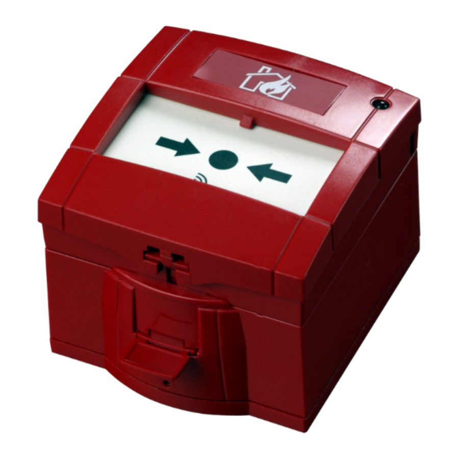
Ensure that all call points are sited in accordance with the survey and design details. All call points must be surface mounted.

Loosen the fixing screw to remove the mounting plate (See figure 1).

Fix the mounting plate, using suitable fixings and fasteners. A minimum of 2 mounting holes must be used (See figure 2).
Countersunk head screws must be used to avoid the possibility of causing damage to the internal components (See figure 3).
When fitting / replacing batteries; observe correct polarity, using only specified batteries.

Connect the power jumper across the PIN header. (See figure 4).
Please see commissioning manual for log on procedure details.
When reassembling the device, observe the hinged connection located on the devices top edge first, prior to closing the unit. Finally lock the call point into the mounting plate by tightening the fixing screw.
XPERT Card Addressing

Select the desired address and remove the pips indicated in black. Remove pips with a small screwdriver.
NOTE: care must be taken to ensure that the correct address is set, prior to insertion.
Device Activation

Device Resetting

XPert Card Removal
![]()
This process will result in the device going into an alarm condition.
Ensure the device is disabled from the system, prior to proceeding.- Simultaneously turn the reset key anti-clockwise...
Whilst pushing the head unit down, to release it from the wireless module.
![]()
- Press the connector retaining clip...
whilst carefully disconnecting the molex connection.
Note: do not pull on the wires.
![]()
- Remove the two screws to release the mounting bracket.
![]()
- Simultaneously disengage the locking mechanism...
whilst carefully pulling the XPert card downwards to remove it from the device.
![]()
- Re-fit the mounting bracket, using both screws.
![]()
- Reconnect the molex connection.
![]()
- Finally slide the head unit back into position.
Note: The XPert card must now be appropriately addressed and re-inserted for correct device operation.
![]()


Specification
| Operating temperature | -10 to 55°C |
| Storage temperature | 5 to 30°C |
| Humidity | Up to 95% non-condensing |
| Supply | 6x AA Alkaline (Panasonic LR6AD Powerline / Varta 4006 Industrial) |
 Fitting of an incorrect battery type invalidates the product certification and may result in poor performance. | |
| IP Rating | IP24 |
| Operating frequency | 868 MHz |
| Output transmitter | Auto adjusting 0 - 14 dBm |
| power | (0 - 25 mW) |
| Dimensions (w) x (h) x (d) | 90 x 98 x 72.5 mm |
| Weight | 0.35 kg |
| Location | Type A: For indoor use |
| Protocol | X5 |
| Programming | PP2289 XPander EPG |
Documents / ResourcesDownload manual
Here you can download full pdf version of manual, it may contain additional safety instructions, warranty information, FCC rules, etc.
Download Apollo XPander, XPA-MC-14101-APO Installation Manual
Advertisement


Need help?
Do you have a question about the XPander and is the answer not in the manual?
Questions and answers