Table of Contents

Related Manuals for Apollo 55000-273


Summary of Contents for Apollo 55000-273
- Page 1 PP2146/2003/Issue 1 FIRE DETECTORS LIMITED INTELLIGENT REFLECTIVE BEAM DETECTOR © INSTALLATION GUIDE Part no 55000-268 (5–50 metres) 55000-273 (50–100 metres) Acorn Fire & Security LTD www.acornfiresecurity.com...
-
Page 2: Table Of Contents
www.acornfiresecurity.com INTELLIGENT REFLECTIVE BEAM DETECTOR GENERAL INFORMATION Description of the ref ective beam detector How does a beam detector work? Automatic reset Drift compensation SYSTEM DESIGN Positioning ref ective beam detectors Spacing Height Pitched roofs and sloping ceilings How many ref ective beam detectors can be connected to a loop? INSTALLING BEAM DETECTORS General Setting the obscuration level... - Page 3 www.acornfiresecurity.com Read this installation guide because… beam detectors are different from point detectors beam detectors need to be aligned, not just installed all engineers need to understand the alignment process by following the advice in this guide you will avoid problems and repeated site vists www.acornfiresecurity.com...
-
Page 4: General Information
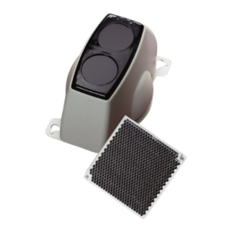
50m, and requires one ref ector. compensation the beam detector transmits a Part no 55000-273 is for distances between 50m fault signal. In the event of a f re being detected and 100m and requires four ref ectors arranged when the beam detector has reached its com- as a square. -
Page 5: System Design
www.acornfiresecurity.com SYSTEM DESIGN Spacing The maximum spacing between the axes of ad- Positioning ref ective beam detectors jacent beam detectors is typically 15m for satis- The intelligent ref ective beam detector must be factory detection under f at ceilings, providing positioned correctly to minimise the detection a maximum total area coverage of 1500 square time. -
Page 6: Height
www.acornfiresecurity.com Height Pitched roofs and sloping ceilings The maximum rec om mend ed installation height In buildings with pitched roofs or ceilings the is generally 25m (some local standards or codes maximum distance either side of the beam in of practice might allow more under certain the apex only may be increased by 1% for each circumstances) and the distance between the degree of ceiling pitch up to a maximum of 25%... -
Page 7: How Many Ref Ective Beam Detectors Can Be Connected To A Loop
Set the beam detector to one of the three ob- negative bi-directional short circuit isolator. For scuration levels shown in Table 2 below. This is details of these please refer to Apollo PIN sheet done with DIL switches 3 and 4 on the back of PP2090. - Page 8 Reflective Beam Detector (XXm) Part No. 55000-XXXAPO Range X-XX metres Refer to Apollo publication : PP2146 EN54-12:2002 Apollo Fire Detectors Ltd. PO9 1JR, England ADDRESS ADDRESS REFER TO APOLLO LOOP PUBLICATION PP2146 CONNECTOR Fig 3 Rear view of intelligent refl ective beam detector...
-
Page 9: Setting The Address
www.acornfiresecurity.com Setting the address The address of the beam detector is set using the DIL switch. The f rst seven segments of the switch are set to ‘0’ or ‘1’ using a s mall screwdriver or similar tool. The eighth segment is not used. A complete list of address settings is shown be- low. -
Page 10: Fitting The Ref Ective Beam Detector
www.acornfiresecurity.com Fitting the ref ective beam detector Remove the detector housing before installation to prevent it becoming dislodged during the in- stallation process. Position the beam and ref ectors on solid struc- tures at between 0.3 and 0.6 metres below ceiling level. -
Page 11: Targeting, Aligning And Commissioning The Reflective Beam Detector
www.acornfiresecurity.com TARGETING, ALIGNING AND COMMISSIONING THE REFLECTIVE BEAM DETECTOR What is ‘targeting’ and ‘aligning’? The ref ective beam detector will work only if the beam of light hits the ref ector and returns to the receiver. The best possible result is achieved if the centre of the beam hits the centre of the ref ector. -
Page 12: Targeting Explained
www.acornfiresecurity.com Targeting explained When the beam detector is set to ‘targeting’ it is automatically switched to full power. The purpose of targeting is to adjust the detector by panning and tilting until the beam shines on the ref ector which then ref ects it back. Progress in targeting is indicated by two LEDs: Fig 9b no LED illuminated if beam hits outer part of... -
Page 13: Targeting Step By Step
www.acornfiresecurity.com Targeting step by step 1. Switch on the beam detector. Push the mode switch (Fig 12) up to ‘prism targeting mode’. 2. Pan and tilt the beam detector, by turning the thumbwheels, until the centre of the beam hits the part of the ref ector shown in Fig 10b, causing the red LED to f ash. -
Page 14: Alignment Explained
www.acornfiresecurity.com Alignment explained Alignment can only be carried out after successful targeting. When the detector is switched to ‘alignment’ the power of the beam is adjusted automatically. The effect of panning or tilting is still indicated by the LEDs but what they are indicating is different from when the detector is switched to ‘targeting’. - Page 15 www.acornfiresecurity.com 2. The purpose of the second stage of alignment is to manually adjust the detector so as to align the centre of the beam as closely as possible with the centre of the ref ector. AMBER LED IMAGINARY LINES INDICATE LED FLASH FLASHES Turn one of the thumbwheels until one of the...
-
Page 16: Stabilisation And Testing
www.acornfiresecurity.com Stabilisation and testing Ref ector test The detector stabilises automatically but it is Cover the ref ector completely with non-ref ective necessary to check the area which is being material. After 15 seconds or sooner the amber protected in order to make quite sure that the LED of the beam detector will f ash. -
Page 17: Commissioning
www.acornfiresecurity.com COMMISSIONING Analogue values The beam detector returns a p re-set analogue value corresponding to its status. These values are def ned in Table 4 below. Analogue value Signif cance Microprocessor fault Sensor fault Prism (ref ector) targeting mode Alignment mode General fault warning ‘Signal High’... -
Page 18: Alarm Test
www.acornfiresecurity.com Alarm test A test f lter with a gradient from 0% to 100% black is supplied to carry out functional tests of the re- f ective beam detector. Select the obscuration mark on the test f lter (Fig 24) that corresponds to the obscuration set as described in page 7. -
Page 19: Protocol Data And Fault Indication
www.acornfiresecurity.com PROTOCOL DATA AND FAULT INDICATION Input/Output bits The ref ective beam detector responds to output bits from the protocol as follows: When output bit 2 is set to logic 1 on two or more consecutive pollings the red alarm LED is illuminated. -
Page 20: Troubleshooting
www.acornfiresecurity.com TROUBLESHOOTING Before investigating individual beam detectors for faults, it is very important to check that the system wiring is fault free. Many fault conditions are the result of simple wiring errors. Earth faults on a data loop or any ancillary zone wiring may cause communication errors. -
Page 21: Spare Parts
Refl ector (prism) for the 100m detector (= 4x 50m refl ector) Test fi lter Technical Data Part no 55000-268 5 to 50 metres (detector to ref ector) Part no 55000-273 50 to 100 metres (detector to ref ector) Supply Voltage 17–28V DC (plus protocol) Supply Current... - Page 22 www.acornfiresecurity.com FIRE DETECTORS LIMITED www.acornfiresecurity.com...
Need help?
Do you have a question about the 55000-273 and is the answer not in the manual?
Questions and answers