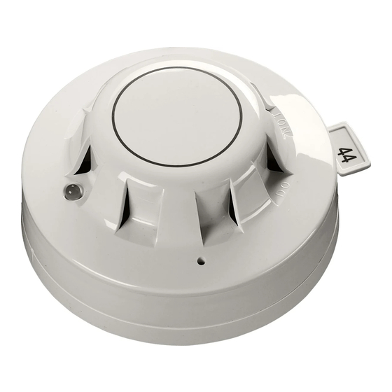
Apollo XP95 Installation Manual
Open-area vad (red flash)
Hide thumbs
Also See for XP95:
- Engineering product manual (25 pages) ,
- Installation manual (18 pages) ,
- Quick start manual (5 pages)
Advertisement
Quick Links
H - The maximum height from floor level in metres at which the VAD may be mounted
D - The diameter in metres of the cylindrical volume covered when the device is mounted to the
ceiling at a height of 3m
Fig. 1 Mounting instruction for ceiling mounted devices
W
W
W
H - The maximum height of the device on the wall in metres with a minimum value of 2.4m
W - The width in metres of the square volume covered when the device is mounted to the
wall at required height
55000-736 / 55000-737 (W-2.4-6) - coverage cuboid volume of 2.4m x 6m x 6m = 86.4m³
Fig. 2 Mounting instruction for wall mounted devices
39215-387/Issue 2A
H
D
3 =150m3
1.
2.
H
Note: Make sure that a mounting base is fitted
in horizontal position as shown above.
4
www.acornfiresecurity.com
XP95 Open-Area VAD (Red Flash) Installation Guide
General
This guide describes the installation of the following Visual Alarm Device (VAD) variants
Part Number
Product Description
55000-736
XP95 Open-Area VAD Cat. W - Red Body (Red Flash) (W-2.4-6)
55000-737
XP95 Open-Area VAD Cat. W - White Body (Red Flash) (W-2.4-6)
55000-738
XP95 Open-Area VAD Cat. C - Red Body (Red Flash) (C-3-8)
55000-739
XP95 Open-Area VAD Cat. C - White Body (Red Flash) (C-3-8)
The XP95 Open-Area VADs can be used in XP95 or Discovery analogue addressable fi re detection
systems.
Note: the XP95 Open-Area VADs are not suitable for outdoor use.
Mounting Instructions
Where installation guidance requires that there cannot be loss of more than one function on a loop, or
fi reproof cable is not used, the VAD must be fi tted to an isolating base, part no 45681-284 or equivalent
in line with PP2090. Be sure to fi t the correct variant for the application. The category "C" or "W" defi nes
the mounting orientation. Do not mount a "C" category to a wall and vice versa.
Particular care should be taken with category "W" devices as these are directional. Failure to
!
mount these correctly could result in reduced coverage
For mounting instruction please see Fig. 1 and Fig. 2 on page 4.
The XP95 Open-Area VAD must be assigned an address by coding the XPERT card in the usual way.
A list of address settings is shown on page 3.
Locking Screw
The VAD can be locked to the base in order to ensure system integrity. The locking screw is in the shoulder
of the VAD. Insert a 1.5mm hexagonal key and turn the screw clockwise to lock the VAD to the base.
Technical Information
Operating Voltage
(Polarity Sensitive)
Current Consumption at 24V:
VAD Operated
Power-up Surge Current
Operating Temperature
Humidity (no condensation)
(Tested and approved by
TraC Global Limited
www.acornfiresecurity.com
17-28 V dc
Quiescent
280 μA
16 mA
1.5 mA for 100 ms
-10°C to +55°C
0-95%
IP Rating
IP21C (in accordance with EN54-23)
IP54
(when used with 45681-210, 45681-284, or SA5000-200 Mounting Base)
IP55
(when used with the Deckhead Mounting Box 45681-217)
Flash Rate
0.5 Hz
*
Tested by Apollo Fire Detectors Limited to -40°C to +70°C
1
Category
W (Wall)
W (Wall)
C (Ceiling)
C (Ceiling)
*
Advertisement

Summary of Contents for Apollo XP95
- Page 1 For mounting instruction please see Fig. 1 and Fig. 2 on page 4. The XP95 Open-Area VAD must be assigned an address by coding the XPERT card in the usual way. A list of address settings is shown on page 3.
- Page 2 Before investigating individual units for faults, it is important to check the system wiring is fault free. Earth faults on data loops may cause communication errors. If an XP95 test set is used to test the VAD please note that constant interrogation of the device will cause a higher than normal fl ash rate and an analogue value of 16.


Need help?
Do you have a question about the XP95 and is the answer not in the manual?
Questions and answers