
Related Manuals for Apollo Discovery ASD-2


Summary of Contents for Apollo Discovery ASD-2
- Page 1 Apollo Discovery ASD-2 Product Guide December 2013 Part Number: 29650-082 Document Number: PP2498...
- Page 3 You acknowledge that you have not relied on any oral or written information, representation or advice given by or on behalf of Apollo Fire Detectors or its representatives.
- Page 4 Discovery ASD-2 Product Guide Apollo Fire Detectors Document Conventions The following typographic conventions are used in this document: Convention Description Bold Used to denote: emphasis. Used for names of menus, menu options, toolbar buttons Italics Used to denote: references to other parts of this document or other documents.
-
Page 5: Table Of Contents
Apollo Fire Detectors Discovery ASD-2 Product Guide Table of Contents Introduction Installation Baffles Mounting the Detector Enclosure Wiring Wiring Access Connect Wiring Battery Terminal Pipe Installation Pipe Specification Fixings End Cap with Sampling Hole Bends Exhaust Filters Standard Configurations Set-up... - Page 6 Discovery ASD-2 Product Guide Apollo Fire Detectors This page is intentionally left blank. www.apollo-fire.co.uk...
-
Page 7: Introduction
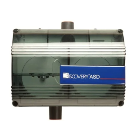
The Apollo Discovery ASD-2 is an aspirating smoke detection system that utilizes an air-sampling pipe network to draw air towards conventional or analog addressable point detectors in an aspirated enclosure. The dual channel Discovery ASD-2 has provision for two separate point detectors, each monitoring a separate sampling pipe run. - Page 8 Discovery ASD-2 Product Guide Apollo Fire Detectors This page is intentionally left blank. www.apollo-fire.co.uk...
-
Page 9: Installation
Figure 2-1: Detector Enclosure Baffles It is necessary to fit baffles to the Discovery ASD-2 system to ensure that the samples airflow is directed towards the point detector. The baffle is shaped to match the point detector and simply clips into position in the slots provided in the transparent lid. -
Page 10: Mounting The Detector Enclosure
Discovery ASD-2 Product Guide Apollo Fire Detectors Mounting the Detector Enclosure Notes: This equipment must be installed by a qualified installer in accordance with all local and national code requirements. The detector assembly must be installed at an accessible position to facilitate maintenance and testing. - Page 11 Apollo Fire Detectors Discovery ASD-2 Product Guide Dimensions: 37.5mm 188.0mm 140.0mm 32.5mm 165.7mm 241.7mm 241.7mm 53.0mm 102.0mm 129.36mm 159.3mm 159.3mm 258.6mm 258.6mm Figure 2-3: Detector Enclosure Dimensions www.apollo-fire.co.uk...
- Page 12 Discovery ASD-2 Product Guide Apollo Fire Detectors This page is intentionally left blank. www.apollo-fire.co.uk...
-
Page 13: Wiring
Apollo Fire Detectors Discovery ASD-2 Product Guide Wiring The following wiring connections must be made to the detector housing: 24V DC Power Supply. Refer to Section 3.3 for further information. This wiring enters the detector housing via cable seals and is connected to the appropriate terminals on the main circuit board or display board. -
Page 14: Battery Terminal
Figure 3-2: Ferrite core and battery supply wiring The Discovery ASD-2 unit is designed to run from a 24 VDC supply. The supply should be connected to the two way BATTERY connector on the main circuit board ensuring that the wires are correctly orientated. The minimum recommended wire size is 16 x 0.25 mm (18 AWG), or larger if the supply is further than 5 m (16.4 ft) -
Page 15: Pipe Installation
(permanent), or socket unions (removable). Note: The Discovery ASD-2 inlet ports are tapered to allow a push fit of the sampling pipe. The pipes should be cut squarely to ensure a good, airtight seal. Solvent adhesive should not be used for this joint. -
Page 16: Exhaust
Apollo Fire Detectors Exhaust Where the Discovery ASD-2 is located outside the protected area, consideration must be given to returning the exhaust air to the protected environment to balance pressure differences that may exist between the two areas. In the majority of applications, this is not necessary as pressure differences are minimal. -
Page 17: Set-Up
Apollo Fire Detectors Discovery ASD-2 Product Guide Set-up Display Functions Each channel has the following functional LEDs. BARGRAPH of AIRFLOW SPEED 2, 3, AIRFLOW OK, HIGH AIRFLOW, LOW AIRFLOW The following LEDs are common to both channels. POWER ON GENERAL FAULT (Mains PSU Option Only) -
Page 18: User Functions
Discovery ASD-2 Product Guide Apollo Fire Detectors User Functions Press and hold SELECT and CHANGE keys simultaneously for 1 sec to initialize function selection. Press and release SELECT key to sequentially step through functions. Press and release CHANGE key to modify setting. - Page 19 Apollo Fire Detectors Discovery ASD-2 Product Guide A description of Discovery ASD-2 user functions are shown in the following table. Table 5-1: User Functions for the Discovery ASD-2 System Function Display Special Instructions Set fan speed POWER LED flashes Set sensitivity of bar graph in...
-
Page 20: Set-Up Notes
(e.g. prison cell applications) then it may be necessary to increase the delay between when flow limit has been exceeded and instigating a FLOW FAULT condition. Table 5-2: Flow Delay Settings for the Discovery ASD-2 system Bargraph LED Flow into Fault Delay (Seconds) -
Page 21: Testing
Apollo Fire Detectors Discovery ASD-2 Product Guide Testing Note: Testing should only be carried out by qualified personnel. Ensure that the proper authorities have been informed and that the unit has been isolated from the fire system if necessary to prevent unwanted alarms. - Page 22 Discovery ASD-2 Product Guide Apollo Fire Detectors This page is intentionally left blank. www.apollo-fire.co.uk...
-
Page 23: Maintenance
Point detectors should be serviced in accordance with the manufacturer's recommendations. To remove and replace the point detector: 1. Disconnect power from the Discovery ASD-2. 2. Loosen the four screws that secure the clear plastic cover to the housing base. - Page 24 Discovery ASD-2 Product Guide Apollo Fire Detectors This page is intentionally left blank. www.apollo-fire.co.uk...
-
Page 25: En54-20 Certified Detectors
Apollo Fire Detectors Discovery ASD-2 Product Guide EN54-20 Certified Detectors The Discovery Optical point detector has been independently tested and certified for use in the Discovery ASD-2 system and is suitable for EN54-20 approved Class C installations. The following table shows the limits that should not be exceeded if the installation is to conform to Class C requirements. - Page 26 Discovery ASD-2 Product Guide Apollo Fire Detectors This page is intentionally left blank. www.apollo-fire.co.uk...
-
Page 27: Problem Solving
Apollo Fire Detectors Discovery ASD-2 Product Guide Problem Solving Problem Possible Solutions Power light flashing. Ensure supply to BATTERY connector within limits. No lights on display. Ensure supply leads correctly orientated. Ensure that BAT FUSE Fan not running. correctly seated in socket and fuse not blown. - Page 28 Discovery ASD-2 Product Guide Apollo Fire Detectors This page is intentionally left blank. www.apollo-fire.co.uk...
-
Page 29: 10 Specifications
Apollo Fire Detectors Discovery ASD-2 Product Guide 10 Specifications Number of Point Detectors 2 Discovery Opticals Dimensions 258.6 mm x 165.7 mm x 320.6 mm Filtration Single stage dust particle filter Flow Monitoring Thermal device, high and low thresholds. 10 element bar graph indication. - Page 30 Discovery ASD-2 Product Guide Apollo Fire Detectors Xtr D/N 26328_00 Xtr P/N 30498 www.apollo-fire.co.uk...
Need help?
Do you have a question about the Discovery ASD-2 and is the answer not in the manual?
Questions and answers