Advertisement
Advertisement
Table of Contents

Related Manuals for Apollo SA7100-100APO


Summary of Contents for Apollo SA7100-100APO
- Page 1 Apollo Intelligent Auto Aligning Beam Detector User Guide...
-
Page 2: General Information
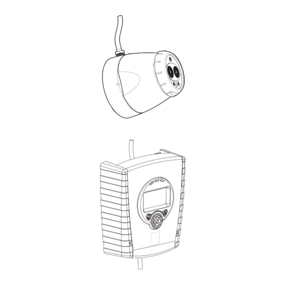
1. General Information 50cm 50cm 50cm 50cm 8-100m 8-100m Mount on solid surfaces (structural wall or girder) Ensure clear line of sight from Detector to Reflector 50—100m = 4 18—50m = 1 8—18m = 1 Use Short Range Mask • All installations should comply with local regulations •... - Page 3 2. Fitting the Product Clip PCB into base Insert Detector cable LED indicator must face downward...
-
Page 4: Wiring Diagram
3. Wiring Diagram It is possible to wire either one or two detectors onto one controller. Refer to section 4. Address Settings for further information on how to select addresses for each detector. -
Page 5: Address Settings
4. Address Settings Select the required address using address switches 1 to 7 for XP/Discovery and 1 to 8 for Soteria with core enabled panel. The reference table can be viewed below, addresses 127-254 relate only to Soteria. When only one detector is connected it will appear on the address set on the DIP switch. -
Page 7: Apply Power
5. Apply power NOTE: One System Controller can be used to control and monitor up to two Detector heads. The ‘#’ symbol in this guide is used to represent the number of the Detector currently selected (1 or 2). 5 seconds 5 seconds 5 seconds •... - Page 8 6. Enter Pass Code to Access Engineering Menu Press for Pass Code screen: • Default Pass Code: 1 2 3 4 • Change digit • Move between digits • Accept • An incorrect Pass Code will return the display to the Pass Code entry screen •...
-
Page 9: Select Detector
8. Select Power Mode • In ‘Hi A’ mode (default), during normal operation the system will take 5.5mA if one Detector is connected or 8mA if two Detectors are connected. During Laser targeting, Auto, Hand and Home functions, the system will take 36mA. •... - Page 10 11. LASER Targeting The system will signal Fault while in this mode The LASER is used to align the Detector with the Reflector. It is an approximate alignment tool only. After Auto-Align the LASER will not necessarily be pointing on the Reflector •...
- Page 11 13. ‘Set’ 0/100 (Calibrate) • When ‘Set’ is displayed press whilst the Reflector is still uncovered • When ‘S-00’ is displayed, cover the Reflector with a non- reflective material and leave covered, then press • When ‘S-01’ is displayed, uncover the Reflector and leave uncovered, then press •...
- Page 12 15. Manual Fire and Fault Tests After installation or cleaning, it is recommended that a manual Fire and Fault test is performed: Fire Test: Cover the Reflector slowly so that it takes longer than 5 seconds to cover. The System Controller will signal Fire to the Fire Control Panel after the delay to fire has expired (10s default) Fault Test: Cover the Reflector completely within 2 seconds.
- Page 13 17. Fire Threshold This setting is the threshold at which the Detector will detect a fire Default factory setting=35% (Set for each Detector) • Sensitivity can be adjusted in 1% steps by pressing up or down keys • Press to accept setting EN Approved Sensitivity Ranges: Complies with EN54-12 for sensitivity levels between 25% and 35% with a maximum delay to fire of 20 seconds...
- Page 14 19. Fire/Fault Delay These settings are the delays that the System Controller uses before signalling a FIRE or FAULT condition respectively to the Fire Control Panel. Default factory setting=10 seconds (Set for each Detector) Delay 2 (Fault) Delay 1 (Fire) 20.
-
Page 15: Cleaning The System
22. Cleaning the System The system will automatically compensate for dust build-up by changing the Compensation Level. However, it is recommended that the Detector lenses and the Reflector are cleaned periodically with a soft lint-free cloth. If the Compensation Level for a particular Detector remains above 130 for several days, this indicates that cleaning should take place on that Detector. -
Page 16: Event Logger
23. Event Logger The System Controller contains a logging function which will store information for the most recent 50 events on each Detector. To access the event log, press tick on the Event Logger icon when the relevant detector is highlighted: Event Code... - Page 17 23. Event Logger (continued) Press left to access older events, and right to access newer events. When the relevant event is selected, press down to access further information about the event. Time elapsed since event started. ‘—‘ will be displayed if the event occurred prior to the most recent power cycle.
- Page 18 24. Troubleshooting - LASER not visible If it is not possible to see the LASER because of the installation environment (for example, if you cannot see the Reflector from the System Controller or there is high ambient light) then use ‘Hand’ Alignment. This option displays the signal strength value returned by the Detector, and allows the user to move the beam 1.
- Page 19 25. Troubleshooting - HOME If it is not known where the beam is pointing, use Home Position to automatically steer the infrared beam to approximately the centre of its range of movement. • Press to exit this function • This will take up to 3 minutes to complete •...
-
Page 20: Troubleshooting Error Codes
26. Troubleshooting - Error Codes • Ensure clear line of sight • Refer to manufacturer for AIM not from Detector to Reflector for E-00 recognised technical assistance a radius of 0.5m Reflector Not • Ensure correct distance has Found during E-10 been selected •... -
Page 21: Technical Specifications
24—14 AWG Cable Gauge 0.5—1.6 mm Housing Flammability rating UL94 V0 This detector incorporates a Soteria isolator and follows the specification as listed in Apollo publication PP2090, except for minimum ‘on’ resistance (Zc) which is 0.2Ω. Width, Height, Depth, Weight,... -
Page 22: Equipment Disposal
27. Equipment Disposal Products marked with this symbol cannot be disposed of as unsorted municipal waste in the European Union. For proper recycling, return this product to your local supplier upon the purchase of equivalent new equipment, or dispose of it at designated collection points. For more information see: www.recyclethis.info. - Page 24 Document Number: 0044-069-01-EN 39215-002/Issue 1...
Need help?
Do you have a question about the SA7100-100APO and is the answer not in the manual?
Questions and answers