
Related Manuals for ProLights ECLFS


Summary of Contents for ProLights ECLFS
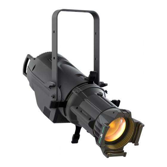
- Page 1 ECLFS LED PROFILER ECLFS OPTIC 14° / 19° / 26° / 36° / 50° USER MANUAL MANUALE UTENTE EN - IT...
- Page 2 In order to improve the quality of products, PROLIGHTS reserves the right to modify the characteristics stated in this instruction manual at any time and without prior notice.
-
Page 3: Table Of Contents
4. 1 Maintenance and cleaning the unit 4. 1 Maintenance and cleaning the unit 4. 2 Fuse replacement 4. 2 Fuse replacement 4. 3 Trouble shooting 4. 3 Trouble shooting Packing content • ECLFS • Power cable • User manual... -
Page 4: General Instructions
ECLFS WARNING! Before carrying out any operations with the unit, carefully read this instruction manual and keep it with cure for future reference. It contains important information about the installation, usage and maintenance of the unit. SAFETY General instruction • The products referred to in this manual conform to the European Community Directives and are there- fore marked with . -
Page 5: Technical Drawing
ECLFS - 1 - TECHNICAL DRAWING ECLFS + OPTIC Technical drawing Fig.1 1.1 CONFIGURATIONS Con guration Middle part, compatible with Re ector Housing 14°, 19°, 26°, 36°, 50° optics ECLFS Optics for ECL pro ler, Optics for ECL pro ler, 14°... -
Page 6: Operating Elements And Connections
2. LOCKING KNOB for the mounting bracket used to access the control panel functions 3. HANDLE and manage them. 4. ECLFS 12. POWER OUT (PowerCON OUT): connect to 5. SAFETY EYE to attach safety cable. supply power to the next unit. -
Page 7: Installation
2.1 MOUNTING ECLFS may be set up on a solid and even surface. The unit can also be mounted upside down to a cross arm. For xing, stable mounting clips are required. The mounting place must be of su cient stability and be able to support a weight of 10 times of the unit’s weight. -
Page 8: Functions And Settings
ECLFS - 3 - FUNCTIONS AND SETTINGS 3.1 OPERATION Connect the supplied main cable to a socket (100-240 VAC-50/60 Hz). Then the unit is ready for operation and can be operated via a DMX controller or it independently performs its show program in succession. -
Page 9: Menu Structure
ECLFS 3.3 MENU STRUCTURE MENU ð ð CONNECT DMX Address Value (1-512) Default: 5CHRGBL ð DMX Mode 3CHRGB 4CHRGBL 5CHRGBL 13CH Tungsten (De ne by Static=>Tungsten) 1CH-3200K 1CH-5400K 1CH-6500K ð RDM ID Name ECLFS ð RDM Mode Mode1/Mode2 Default: Mode1... - Page 10 ECLFS ð INFORMATION XXXX(Hours) Time Info. Current XXXX(Hours) Temperature Fixture Life Factory Cal Near Lamp Temp Factory RDM Software Ver 1U01 V1.0.00 ð ð STATIC Play DMX Receive Slave Receive ð Master / Alone / DMX Presets ð Master / Alone / DMX Color MIX ð...
- Page 11 ECLFS ð ð DEFAULT Basic Reload On/O ð Program Reload On/O Password ð Private Reload On/O Recover calibration and RDM PID code ð All Reload On/O Recover calibration and RDM PID code...
-
Page 12: Static Mode
• Select the desired DMX con guration (1CH - 2CH - 3CH - 3CHRGB - 4CH RGBL - 5CH - 5CHRGBL - 8CH - 13CH, TUNG- STEN - 3200K - 5400K - 6500K) through the buttons UP/DOWN. The tables on page 15 indicate the operating mode and DMX value. The ECLFS is equipped with 5-pole XLR connections. -
Page 13: Fixture Id And Rdm
ECLFS Number of Start address DMX Address Next possible start Next possible start Next possible start DMX channels (example) occupied address for unit No. 1 address for unit No. 2 address for unit No. 3 33-34 33-35 33-36 33-37 33-40... -
Page 14: Connection Of The Dmx Line
ECLFS 3.9 CONNECTION OF THE DMX LINE DMX connection employs standard XLR connectors. Use shielded pair-twisted cables with 120 imped- ance and low capacity. The following diagram shows the connection mode: DMX - INPUT DMX - OUTPUT XLR plug XLR socket... -
Page 15: Dmx Control
ECLFS 3.11 DMX CONTROL Channel FUNCTION Value Tun 3200K 5400K 6500K 1CH 8CH 13CH RGBL RGBL Dimmer Dimmer(Close to Open) 000 - 255 Dimmer ne Dimmer ne 0->100% 000 - 255 CTC Preset 2000K 000 - 022 2000K->2700K 023 - 057 2700K->3200K... - Page 16 ECLFS Theatre 20 CH mode FUNCTION Value Shutter Close 000 - 001 Strobe from slow to fast 002 - 062 Open 063 - 064 Pulse in from slow to fast 065 - 125 Open 126 - 127 Pulse out from slow to fast...
- Page 17 ECLFS Theatre 20 CH mode FUNCTION Value Virtual Color 1 No Function White presets Function 2000K 000 - 022 2000K->2700K 023 - 057 2700K->3200K 058 - 090 3200K->4200K 091 - 139 4200K->5600K 140 - 185 5600K->8000K 186 - 234 8000K->10000K...
-
Page 18: Setup
ECLFS 3.12 SETUP You can change the parameters for the device by following these steps: Temperature Through the Max Temperature function can be displayed the temperature inside the xture, near the lamp. • Press the MODE button so many times until the display shows SETUP, then press the button ENTER. -
Page 19: Fixture Information
ECLFS • Press the button UP/DOWN to select Dimmer1 - Dimmer2 - Dimmer3 - Dimmer4. • Press ENTER button to store. • Press the MODE button to go back or to meet the waiting time to exit the setup menu. -
Page 20: Maintenance
ECLFS - 4 - MAINTENANCE 4.1 MAINTENANCE AND CLEANING THE UNIT • Make sure the area below the installation place is free from unwanted persons during setup. • Switch o the unit, unplug the main cable and wait until the unit has cooled down. - Page 22 Music & Lights S.r.l. si riserva ogni diritto di elaborazione in qualsiasi forma delle presenti istruzioni per l’uso. La riproduzione - anche parziale - per propri scopi commerciali è vietata. Al ne di migliorare la qualità dei prodotti, la Music&Lights S.r.l. si riserva la facoltà di modi care, in qualunque momento e senza preavviso, le speci che menzionate nel presente manuale di istruzioni.
-
Page 23: Eclfs
4. 1 Manutenzione e pulizia del sistema ottico 4. 1 Manutenzione e pulizia del sistema ottico 4. 2 Sostituzione fusibile 4. 2 Sostituzione fusibile 4. 3 Risoluzione dei problemi 4. 3 Risoluzione dei problemi Contenuto dell'imballo: • ECLFS • Cavo di alimentazione • Manuale utente... - Page 24 ECLFS WARNING! Before carrying out any operations with the unit, carefully read this instruction manual and keep it with cure for future reference. It contains important information about the installation, usage and maintenance of the unit. SICUREZZA Avvertenze generali • I prodotti a cui questo manuale si riferisce sono conformi alle Direttive della Comunità Europea e per- tanto recano la sigla .
-
Page 25: Disegno Tecnico
ECLFS - 1 - DISEGNO TECNICO ECLFS + OPTIC Disegno tecnico Fig.1 1.1 CONFIGURAZIONI Con guration Middle part, compatible with Re ector Housing 14°, 19°, 26°, 36°, 50° optics ECLFS Optics for ECL pro ler, Optics for ECL pro ler, 14°... -
Page 26: Elementi Di Comando E Di Collegamento
ECLFS 1. 2 ELEMENTI DI COMANDO E COLLEGAMENTI Rear panel Fig.2 1. STAFFA DI MONTAGGIO pulsanti per accesso e gestione delle diverse 2. MANOPOLA DI FISSAGGIO per la sta a di funzioni montaggio 12. POWER OUT (PowerCON OUT): collegamento 3. MANIGLIA per l'alimentazione all'unità... -
Page 27: Installazione
2.1 MONTAGGIO L’ ECLFS può essere collocato su un piano solido. Inoltre, grazie alle possibilità di ssaggio sulla sta a ( g.3), l’unità può essere montata anche a testa in giù, su una traversa. Per il ssaggio occorrono dei sup- porti robusti per il montaggio. -
Page 28: Funzioni E Impostazioni
Per spegnere l’ ECLFS, staccare la spina dalla presa di rete. Per maggiore comodità è consigliabile collegare l’unità con una presa comandata da un interruttore. 3.2 IMPOSTAZIONE BASE L’ ECLFS dispone di un LCD display e 4 pulsanti per accesso alle funzioni del pannello di controllo e la loro gestione ( g.4). DOWN... -
Page 29: Struttura Menu
ECLFS 3.3 MENU STRUCTURE MENU ð ð CONNECT DMX Address Value (1-512) Default: 5CHRGBL ð DMX Mode 3CHRGB 4CHRGBL 5CHRGBL 13CH Tungsten (De ne by Static=>Tungsten) 1CH-3200K 1CH-5400K 1CH-6500K ð RDM ID Name ECLFS ð RDM Mode Mode1/Mode2 Default: Mode1... - Page 30 ECLFS ð INFORMATION XXXX(Hours) Time Info. Current XXXX(Hours) Temperature Fixture Life Factory Cal Near Lamp Temp Factory RDM Software Ver 1U01 V1.0.00 ð ð STATIC Play DMX Receive Slave Receive ð Master / Alone / DMX Presets ð Master / Alone / DMX Color MIX ð...
- Page 31 ECLFS ð ð DEFAULT Basic Reload On/O ð Program Reload On/O Password ð Private Reload On/O Recover calibration and RDM PID code ð All Reload On/O Recover calibration and RDM PID code...
-
Page 32: Modalità Static
• Attraverso i tasti UP/DOWN selezionare la con gurazione dei canali DMX (1CH - 2CH - 3CH - 3CHRGB - 4CH RGBL - 5CH - 5CHRGBL - 8CH - 13CH, TUNGSTEN - 3200K - 5400K - 6500K). Le tabelle a pagina 16 indicano le modalità operative e i valori DMX. ECLFS è dotato di connessioni XLR a 5 poli. -
Page 33: Fixture Id E Rdm
ECLFS Numero Indirizzo di Indirizzo DMX Prossimo indirizzo di start Prossimo indirizzo di start Prossimo indirizzo di start canali DMX start (esempio) occupati possibile per unità n°1 possibile per unità n°2 possibile per unità n°3 33-35 33-36 33-37 33-40 33-45... -
Page 34: Collegamenti Della Linea Dmx
ECLFS 3.9 COLLEGAMENTI DELLA LINEA DMX La connessione DMX è realizzata con connettori standard XLR. Utilizzare cavi schermati, 2 poli ritorti, con impedenza 120 e bassa capacità. Per il collegamento fare riferimento allo schema di connessione riportato di seguito: DMX - INPUT... -
Page 35: Canali Dmx
ECLFS 3.11 CANALI DMX Channel FUNCTION Value Tun 3200K 5400K 6500K 1CH 8CH 13CH RGBL RGBL Dimmer Dimmer(Close to Open) 000 - 255 Dimmer ne Dimmer ne 0->100% 000 - 255 CTC Preset 2000K 000 - 022 2000K->2700K 023 - 057 2700K->3200K... - Page 36 ECLFS Theatre 20 CH mode FUNCTION Value Shutter Close 000 - 001 Strobe from slow to fast 002 - 062 Open 063 - 064 Pulse in from slow to fast 065 - 125 Open 126 - 127 Pulse out from slow to fast...
- Page 37 ECLFS Theatre 20 CH mode FUNCTION Value Virtual Color 1 On Function White presets Function 2000K 000 - 022 2000K->2700K 023 - 057 2700K->3200K 058 - 090 3200K->4200K 091 - 139 4200K->5600K 140 - 185 5600K->8000K 186 - 234 8000K->10000K...
-
Page 38: Setup
ECLFS 3.12 SETUP È possibile modi care i parametri per il dispositivo seguendo questi passaggi:: Temperature • Tramite la funzione Max Temperature è possibile visualizzare la temperatura all’interno dell’apparecchio, vicino alla lampada. • Premere il pulsante MODE tante volte no a quando sul display non viene visualizzato SETUP, quindi premere il pulsante ENTER. -
Page 39: Advanced
ECLFS • Premere ripetutamente il pulsante MODE per uscire dal menu e salvare le modi che. 3.13 ADVANCED Puoi modi care i parametri seguendo questi passaggi: • Premere il tasto MENU per accedere al menu principale. • Utilizzare i pulsanti UP/DOWN per selezionare ADVANCED. Premere il pulsante ENTER per confermare. -
Page 40: Manutenzione
ECLFS - 4 - MANUTENZIONE 4.1 MANUTENZIONE E PULIZIA DEL SISTEMA OTTICO • Durante gli interventi, assicurarsi che l’area sotto il luogo di installazione sia libera da personale non quali cato. • Spegnere l’unità, scollegare il cavo di alimentazione ed aspettare nché l’unità non si sia ra reddata. - Page 41 Note...
- Page 42 Note...
- Page 44 MUSIC & LIGHTS S.r.l. - Phone +39 0771 72190 - www.musiclights.it...
Need help?
Do you have a question about the ECLFS and is the answer not in the manual?
Questions and answers