
Related Manuals for Titan Performance Series 450e0558067


Summary of Contents for Titan Performance Series 450e0558067
- Page 1 Operating manual Performance Series 450e Airless high-pressure spraying unit Models: 0558067 0558073 Performance Series 450e Edition 9 / 2010 0558 940D...
- Page 2 The operating instructions state that the following points must always be observed before starting up. Faulty units must not be used. Secure Titan spray gun using the safety catch on the trigger. 3. Ensure that the unit is properly earthed. The connection must take place through a correctly earthed two-pole and earth socket outlet.
-
Page 3: Table Of Contents
Contents Contents Page Page Safety regulations for Airless spraying ....... 4 Remedy in case of faults ..........12 Earthing instructions............5 Servicing ...............14 General view of application...........6 10.1 General servicing ............14 Application................6 10.2 High-pressure hose ............14 Coating materials .............6 Repairs at the unit ............14 Description of unit ............6 11.1 Relief valve..............14 Airless process ..............6... -
Page 4: Safety Regulations For Airless Spraying
Safety Regulations Safety regulations for Airless spraying This manual contains information that must be read and understood before using the equipment. When you come to an area that has one of the following symbols, pay particular attention and make certain to heed the safeguard. -
Page 5: Earthing Instructions
Safety regulations General view of application HAZARD: HAZARDOuS VAPORS HAZARD: eXPLOSION HAZARD Due TO INCOMPATIBLe MATeRIALS Paints, solvents, insecticides, and other materials can be harmful if inhaled or come in contact with Will cause severe injury or property damage. body. Vapors can cause severe nausea, fainting, or poisoning. -
Page 6: General View Of Application
Dilutable lacquers and paints or those containing solvents, two- component coating materials, dispersions, latex paints. In the following there is a short description of the technical construction for better understanding of the function. No other materials should be used for spraying without TITAN’s approval. TITAN Performance Series units are electrically driven high- pressure spraying units. A gear unit transfers the driving force to a crankshaft. The... -
Page 7: Legend For Explanatory Diagram Performance Series 450E
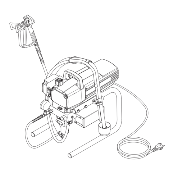
Description of unit Legend for explanatory diagram Performance Series 450e 1 Spray gun 8 Relief valve 2 High-pressure hose Lever position vertical – PRIME ( k circulation) 3 Return hose Lever position horizontal – SPRAY ( p) 4 Suction hose 9 Pressure control knob 5 Frame 10 ON/OFF switch 6 Drip cup 11 Circuit breaker 7 Power cord 12 Pressure gauge 13 Oil cup for Piston Lube (Piston Lube prevents... -
Page 8: Technical Data
Description of unit Starting operation Technical data 5. Fill the oil cup with Piston Lube (Fig. 3). Do not use too much Piston Lube, i.e. ensure that no Piston Lube drips Voltage: 110 Volt AC, 50/60 Hz into the coating material container. Max. current consumption: 9.5 A @ 110VAC Power cord: 3 x 1.5 mm – 6 m Piston Lube prevents increased wear and tear to the packings. -
Page 9: Taking The Unit Into Operation With Coating Material
Spraying Technique Spraying technique Injection hazard. Do not spray without the tip guard in place. NeVeR trigger the gun unless the tip is completely turned to either the spray or the unclog position. ALWAyS engage the gun trigger lock before removing, replacing or cleaning tip. -
Page 10: Handling The High-Pressure Hose
3. Switch the unit ON. 4. Pull the trigger of the spray gun in order to pump the Only use TITAN original-high-pressure hoses remaining coating material from the suction hose, high- in order to ensure functionality, safety and pressure hose and the spray gun into an open container. -
Page 11: Suction Filter
Cleaning the unit (shutting down) Suction filter Cleaning the Airless spray gun 1. Rinse Airless spray gun with an appropriate cleaning agent. A clean suction filter always guarantees maximum feed quantity, constant spraying 2. Clean tip thoroughly with appropriate cleaning agent so pressure and problem-free functioning of the that no coating material residue remains. -
Page 12: Remedy In Case Of Faults
Remedy in case of faults Remedy in case of faults Type of malfunction Possible cause Measures for eliminating the malfunction A. Unit does not start 1. No voltage applied. Check voltage supply. Pressure setting too low. Turn up pressure control knob. 3. ON/OFF switch defective. Replace. B. Unit does not draw in material 1. Relief valve is set to SPRAY (p 1. Set relief valve to PRIME (k circulation). - Page 13 Piston is worn. Remove and replace piston. Increased pulsation at the spray Incorrect high-pressure hose type. Only use TITAN original-high-pressure hoses in order to ensure functionality, safety and durability. Tip worn or too large. Replace tip. Pressure too high.
-
Page 14: Servicing
General servicing remove the front cover. Servicing of the unit should be carried out once annually by the 2. Switch the unit ON and then OFF so that the piston rod is TITAN service. positioned in the lower stroke position. 1. Check high-pressure hoses, device connecting line and plug for damage. Danger of crushing - do not reach with the 2. Check the inlet valve, outlet valve and filter for wear. -
Page 15: Packings
Repairs at the unit 11.3 Packings 1. Remove inlet valve housing in accordance with the steps in Chapter 11.2, Page 14. 2. It is not necessary to remove the outlet valve. 3. Unscrew both cylinder head screws (Fig. 11, Item 1) from the pump manifold (2) with a 3/8 inch hexagon socket head wrench. 4. Slide the pump manifold (2) and piston (3) forward until the piston is out of the T-slot (10) on the slider assembly (5). -
Page 16: Replacing The Motor Assembly
Repairs at the unit 15. Guide piston (3) through the lower packings (9) into the 14. Reconnect the wires (refer to the electrical schematic in pump manifold (2) from below. Using a rubber mallet, the section 11.8 of this manual). lightly tap the piston (3) from below until it can be seen 15. Slide the motor cover (2) over the motor. Secure the above the pump manifold. motor cover with the four motor cover screws (1). 16. Remove installation tool from piston (3). 17. Carefully tighten retainer nut (6) with adjusting wrench. 18. Slide the top of the piston (3) into the T-slot (10) on the slider assembly (4). 19. Position the pump manifold (2) underneath the gear unit housing and push up until it rests against the gear unit housing. 20. Attach pump manifold (2) to the gear unit housing. Ensure that the pressure sensor does not damage the pressure sensor seal (10). -
Page 17: Replacing The Gears
Repairs at the unit 11.6 Replacing the Gears 11.7 Replacing the Transducer 1. Open the relief valve, valve position PRIME (k 1. Open the relief valve, valve position PRIME (k circulation), switch the unit OFF, and unplug the power circulation), switch the unit OFF, and unplug the power cord. cord. 2. Loosen and remove the four motor cover screws (Fig. 16. 2. Loosen and remove the four front cover screws (Fig. 17, 1). Remove the motor cover (2). Item 1). Remove the front cover (2). 3. Disconnect the black and red wires coming from the gear 3. Stop the sprayer at the bottom of its stroke so that the box housing. -
Page 18: Performance Series 450E Connection Diagram
Repairs at the unit 11.8 Performance Series 450e connection diagram Performance Series 450e... -
Page 19: Accessories For Performance Series 450E
Accessories Appendix Accessories for Performance Series 450e Liquid Shield Plus Airless Tip Selection Cleans and protects spray systems against Tips are selected by the orifice size and fan width. The proper rust, corrosion and premature wear. Now with selection is determined by the fan width required for a specific -25º anti-freeze protection. job and by the orifice size that will supply the desired amount of fluid and accomplish proper atomization. Part # Description For light viscosity fluids, smaller orifice tips generally are desired. 314-483 4 ounce (112 ml) bottle For heavier viscosity materials, larger orifice tips are preferred. 314-482 1 liter bottle Please refer to the chart below. Piston Lube Do not exceed the sprayer’s recommended tip size. -
Page 20: Spare Parts List For Main Assembly
Spare parts list Performance Series 450e Main Assembly BS4343 NEMA 5-15P 0558 466 800-741 ~110V ~120V 20 Ft. 8.25 Ft. 4343 NEMA 5-15P 58 466 800-741 110V ~120V 0 Ft. 8.25 Ft. Performance Series 450e... - Page 21 Item Part No. Description Item Part No. Description 0558 302 Motor shroud 0509 218 Screw (4) 9805 287 Screw (4) 0558 301 Face plate 0558 555 Power cord jumper* 0558 263A Fluid section assembly 0551 714 Cord grip 0507 931 Cam base 9805 259 Ground screw 5006 543 Groove pin...
-
Page 22: Spare Parts List For Fluid Section
Spare parts list Performance Series 450e Fluid section Performance Series 450e... - Page 23 Item Part No. Description 0509 594 Retainer 0509 584 Piston guide ------- Upper packing 0551 535 Spacer 0551 112 Transducer assembly 806-106 Pump manifold 0509 873 Fitting 0507 690 Bypass valve assembly 0507 745 Gasket ------- Lower packing (2) 0290 277A Piston rod 806-309 Upper cage 0551 263...
-
Page 24: Spare Parts List For Drive Assembly
Spare parts list Performance Series 450e Drive Assembly Item Part No. Description 0558 316 Housing assembly 0508 573 Thrust washer 0508 572A Gear/crankshaft assembly 0509 121 2nd stage gear 0558 353A Motor assembly, 120V 9820 213 Washer (4) 9800 341 Screw (4) 0508 208 Slider assembly 9850 936 Power switch... -
Page 25: Spare Parts List For Motor Assembly
Spare parts list Performance Series 450e Motor Assembly Item Part No. Description 0522 100 Capacitor assembly 806-304 Fan shroud (2) 704-322 Screw (2) 806-308 9804 916 Screw 0551 543 Tie wrap 0551 540 Motor, Labyrinth Kit assembly, 120V Performance Series 450e... -
Page 26: Spare Parts List Of Frame
Spare parts list Performance Series 450e Stand Item Part No. Description 0508 377 Cord holder 806-071 Leg, left 9885 546 Plug (2) 0551 527 Screw 0509 856 0290 234 Leg, right 806-216 Tube clip 0551 434 Screw 0508 381 Drip cup 9805 230 Screw 9885 546... -
Page 27: Spare Parts List For Suction System
Spare parts list Performance Series 450e Suction system Item Part No. Description 0551 706 Siphon hose 9850 638 Tie wrap (2) 0551 707 Retun tube 0279 459 Clip 0551 705 Siphon tube assembly (includes items 1-4) Performance Series 450e... -
Page 28: Warranty
This warranty does not apply in the case of damage or wear caused by abrasion, corrosion or misuse, negligence, accident, faulty installation, substitution of non-Titan component parts, or tampering with the unit in a manner to impair normal operation. Defective parts are to be returned to an authorized Titan sales/service outlet. All transportation charges, including return to the factory, if necessary, are to be borne and prepaid by the End User. Repaired or replaced equipment will be returned to the End User...
Need help?
Do you have a question about the Performance Series 450e0558067 and is the answer not in the manual?
Questions and answers