Advertisement
www.avtronencoders.com
Nidec Industrial Solutions
243 Tuxedo Avenue | Cleveland, Ohio 44131
encoderhelpdesk@nidec-industrial.com
+1 216-642-1230
ENCODER INSTRUCTIONS
DESCRIPTION
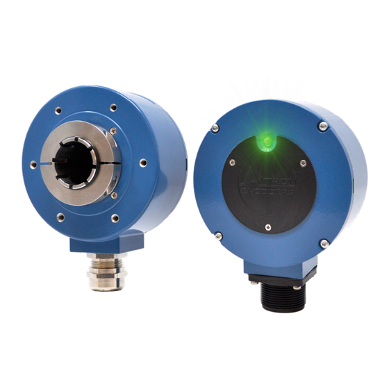
The Avtron Model HS35X Hollow Shaft Rotary Incremental
Encoder is a speed and position incremental transducer (also
known as tachometer or rotary pulse generator). When mounted
to a motor or machine, its output is directly proportional to shaft
position (pulse count) or speed (pulse rate). The HS35X operates
down to zero speed and can be used for both control and
instrumentation applications.
The HS35X employs a hollow shaft and clamping collar to secure
the encoder to the shaft. Optional high-performance resin hollow
shaft insert provide electrical isolation from motor shaft currents
and permits models to fit a broad range of shaft sizes from 1/2" to
1" [11mm - 25mm] by adapting the native 1" bore size.
An anti-rotation bracket prevents rotation of the encoder while
allowing for shaft end float and axial movement. An optional
protective basket kit offers additional protection from impact and
motor lifting damage. The HS35X encoder offers 2Ø outputs (A, B)
90° apart for direction sensing (A Quad B), with complements
(A/, B/) and with marker pulse and complement (Z, Z/)
H S 3 5 X
Output
Line
Model
PPR
Driver
HS35X
G- 100
1- 5-30V in / out
H- 120
2- 5-30V in / 5V out
K- 200
3- 5V in / 5V out
L- 240
M- 250
E- 360
K- 400
Q- 500
R- 512
S- 600
V- 900
W- 1000
Y- 1024
Z- 1200
U- 1800
3- 2000
4- 2048
5- 2500
D- 4096
8- 4800
9- 5000
2- 8192
1- 10000
0- Special
HS35X PART NUMBERS AND AVAILABLE OPTIONS
Connector
Bore Size
Options
USA
A- 10 Pin MS, w/o Plug, Avtron Phasing
B- 1/2"
B- 10 Pin MS, w/o Plug, Reverse Phasing
C- 5/8"
C- 10 Pin MS, w/ Plug, Avtron Phasing
D- 3/4"
D- 10 Pin MS, w/ Plug, Reverse Phasing
E- 7/8"
E- 6 Pin MS, w/o Plug, Avtron Phasing
F- 1" (Native Bore)
F- 6 Pin MS, w/o Plug, Reverse Phasing
U- Universal USA
G- 6 Pin MS, w/ Plug, Avtron Phasing
H- 6 Pin MS, w/ Plug, Reverse Phasing
1/2"-7/8" via inserts
(Native 1" bore)
T- M12/8 Pin Turck Pinout, w/o Plug,
Avtron Phasing
METRIC
U- M12/8 Pin US Pinout, w/o Plug, Avtron
N- 11mm
Phasing
P- 12mm
V- M12/8 Pin US Pinout, w/ Plug, Avtron
Q- 14mm
Phasing
R- 15mm
2- M12/8 Pin US Pinout, w/ Plug, Reverse
S- 16mm
Phasing
V- 19mm
W- M20 Cord Grip w/ 18" Cable
W- 20mm
Y- 25mm (Native Bore)
Z- Universal Metric
12-20mm via inserts (Native 1" Bore)
HS35X
INSTALLATION CONSIDERATIONS
See page 2 and drawing on page 7 for shaft engagement rules.
The motor shaft may include a keyway, but the key must be
removed prior to installation as the HS35X does not support the
use of a key.
The HS35X offers optional Avtron flexible anti-rotation tethers/
brackets which will permit the encoder to tolerate ±0.01" of
shaft end float/axial movement. Select the proper tether for the
application from the table below.
CAUTION:
Be careful not to damage the clamping fingers of the
hollow shaft during handling. Do not tighten clamping
collar before installation onto motor shaft.
WARNING:
Installation should be performed only by qualified
personnel. Safety precautions must be taken to ensure
machinery cannot rotate and all sources of power are
removed during installation.
WARNING:
Be certain to identify thread locker and anti-seize
compound correctly. Using anti-seize in place of thread
locker can cause mechanical failure leading to equipment
failure, damage, and harm to operators.
Mounting
Protection
Style
U- Universal End-of-
0- None
1- Basket
Shaft & Thru-Shaft
X- Thru-Shaft (No
Cover)
HS35X
Hollow Shaft Magnetic
Incremental Encoder
Tether Options
Channels
X- None
A- A, A/, B, B/, Z, Z/
A- Fan Cover 1/4-20
B- A, A/, B, B/
B- Fan Cover 5/16-18
D- A, A/
C- Fan Cover 3/8-16
E- A, B, Z
D- Fan Covers (A+B+C)
F- A, B
E- 4.500 C-Face
F- 8.500 C-Face
G- 12 in. (300mm) Threaded Rod
Torque Arm
M- D + E
P- 115mm Threaded Rod Torque
Arm
R- Pin & Block
T- 3 in. (76mm) Threaded Rod
Torque Arm
U- D + E + F
Rev: 005
Special
Features
000- None
4xx- Special PPR
9xx- Special Cable
Length xx=Feet
090- IP66 Rated
Sealing
1
Advertisement
Table of Contents

Related Manuals for Avtron HS35X


Summary of Contents for Avtron HS35X
- Page 1 The motor shaft may include a keyway, but the key must be known as tachometer or rotary pulse generator). When mounted removed prior to installation as the HS35X does not support the to a motor or machine, its output is directly proportional to shaft use of a key.
-
Page 2: Installation
1.75” [44mm] for models using a sizing insert. See wiring diagram on page 4 for encoder connector pinouts. The HS35X encoder can be wired for single phase or two-phase operation, either with or without complements, with or without markers. See connector options and wiring diagrams. -
Page 3: Troubleshooting
RPM, PPR, output voltage and cable capacitance. Line driver option “2” permits the longest cable lengths (up to 1000 ft (330m) at 45kHz). All HS35X line drivers have full protection against external faults. These factors may dictate maximum potential cable lengths. - Page 4 Standard Phasing. For Connector Options with Reverse Phasing, B Leads A for CW rotation, viewed from the back of the encoder (LED side). PLEASE NOTE: As of Rev F, phasing has been updated to be viewed from the back of the encoder. For any HS35X Encoder prior to Rev F (Rev E or lower, Serial # 1012 or lower), phasing was viewed from the front (clamp end) of the encoder.
-
Page 5: Specifications Table
Mis-Wiring +V out Output voltage equal to input voltage Alarm Alarm Open collector, normally off, goes low on alarm, sink 100mA max, 50VDC max Marker One per revolution, 1/4 AB Cycle Sync with A & B High HS35X Rev: 005... - Page 6 SHAFT KIT DESCRIPTION STYLE U A34966-1 1/2" A34966-2 5/8" A34966-3 3/4" A34966-4 7/8" A40434-U Universal US (1/2" to 7/8") A40500-N 11mm A34966-5 12mm A34966-9 14mm A34966-6 15mm A34966-7 16mm A34966-10 19mm A34966-8 20mm A40434-Z Universal Metric (12mm-20mm) HS35X Rev: 005...
-
Page 7: Outline Drawings
1.75 [44mm] min. CONNECTORS CABLE OPTION: W 10 PIN MS OPTIONS C & D MS OPTIONS A & B (18" STANDARD LENGTH) (WITH PLUGS) (W/O PLUGS) Also available assembled with cable: CBL1BBA18PWyyy.y TETHERS OPTION “E” OPTION “F” HS35X Rev: 005... - Page 8 OUTLINE DRAWINGS CONT’D TETHERS CONT'D OPTION “R” HS35X Rev: 005...
- Page 9 Use a knife or file to remove any sharp edges. MODEL SECTION TO BE REMOVED HS25A HS35A None HS35M B (2 Places) HS35X None For installation of the protective guard, the encoder tether must be installed first. See Tether Install on page 10 for details. HS35X Rev: 005...
- Page 10 Ensure that the shaft is clean and free of burrs. Loosen the machine. encoder shaft collar. Do not apply threadlocker to HS35X. Slide the encoder onto the shaft until the tether meets the mounting surface or maximum engagement has been reached. Shaft engagement must meet the minimum requirements established in the encoder installation instructions.
Need help?
Do you have a question about the HS35X and is the answer not in the manual?
Questions and answers