Advertisement
Quick Links
Nidec Makes the Most Reliable Encoders in the World
2 4 3 T u x e d o A v e n u e
e n c o d e r h e l p d e s k @ n i d e c - i n d u s t r i a l . c o m
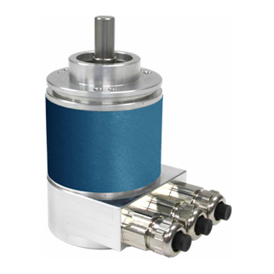
DESCRIPTION
The Avtron Model AV6A is a light mill duty absolute encoder. It
expresses the position of rotation as an output message or value.
AV6A can measure a single turn of rotation or multiple rotations. The
AV6A measures the shaft rotation and position without the need for
external power or internal batteries or capacitors through its multi-
turn gear system. The AV6A operates down to zero speed and can be
used for both control and instrumentation applications.
CAUTION
Do not utilize AV6A in hazardous locations which
require ATEX, UL, CUL, CSA, or other explosion protection
certification. AV6A is not certified for hazardous
locations.
The AV6A is designed for mounting on flanges (58mm, 36mm,
1.25"), or on a foot mount bracket for coupling. The AV6A is not
recommended for pulley or chain drive applications.
SAFETY
The AV6A is not considered as a safety device and is not suitable for
connection into a safety system.
AV6A PART NUMBERS AND AVAILABLE OPTIONS
Model
Bus
Flange
AV6A
C- CANOpen
1- 58mm "servo/
clamp" flange,
D- DeviceNet
36mm male
K- POWERLINK
pilot, 3X M3,
L- Parallel
3X M4 at
M- ModbusTCP
48mm
Ethernet
2- 58mm
N- Profinet IO
"synchro"
P- Profibus DP
flange, 50mm
R- Ethernet/IP
male pilot,
S- SSI
3X M4
at 42mm
4- 2.5" square
flange
w/1.25" male
pilot
FLANGE COMPATIBILITY
Flange
1
2
4
X - no seal option not recommended
+
w w w . a v t r o n e n c o d e r s . c o m
|
C l e v e l a n d , O h i o 4 4 1 3 1
|
Turns/
Shaft Size
bits
B- 3/8" dia. x
X- 0/0-
E- 256/8**
5/8" w/flat
single turn
F- 512/9**
C- 10mm dia. x
A- 16/4**
0- 1024/10**
20mm w/flat
D- 128/7**
2- 4096/12
T- 6mm dia., x
E- 256/8**
3- 8192/13
10mm, no flat
2- 4096/12
4- 16384/14
4- 16384/14
6- 65536/16
**Parallel Bus Only
Shaft
IP/Sealing
Bus
C
X
, A, S
+
CANOpen
C, T
X
, A, S
+
DeviceNet
B
X
, A, S
+
POWERLINK
Parallel
ModbusTCP
Profinet
Profibus DP
EtherNet/IP
SSI
* Not all turns/bits can be combined with PPR/Bits. Contact factory for all valid combinations.
+ 1 2 1 6 - 6 4 2 - 1 2 3 0
WARNING
Installation should be performed only by qualified
personnel. Safety precautions must be taken to ensure
machinery cannot rotate and all sources of power are
removed during installation.
INSTALLATION
Refer to the back page of these instructions for outline and mounting
dimensions.
Equipment needed for installation
Supplied:
AV6A Encoder
Optional:
(none)
Not Supplied:
Open Wrenches, Hex Wrenches, Dial Indicator Gauge
Caliper Gauge, Coupling, Foot Mount and Mounting Screws
PPR/bits
Connector
Connector
per turn
A- 1xM12/5 pin
A- side/radial
B- 2xM12/5 pin
E- end/axial
C- 3xM12 4/4/5
or 4/4/4 pins
D- 2xM12/4/5 pin
E- M12/8 pin
F- M23/12 pin
G- M27/26pin
J- 2x cable entry
K- 3x cable entry
M- M23/8pin Hengstler
N- M23/8pin Stegmann
Q- M23/8pin Kubler
W- Cable, 1m
STANDARD CONNECTORS & OUTPUT FORMATS
Turns/
Code
Bits*
C
12, 14
D
12, 14
K
12, 14
4, 7, 8,
L
12
M
12, 14
N
12, 14
P
12, 14
R
12, 14
4, 8, 12,
S
14
AV6A
1
Encoder Instructions
MODEL
AV6A
ABSOLUTE OPTICAL
SOLID SHAFT ENCODER
IP
Output
Exit
Rating
1- Binary
X- None, IP54
A- IP66 shaft seals
2- Gray
S- IP66 seals,
stainless
housing
PPR/Bits*
Connectors
12, 13, 16
A, B, C, J, K, W
12, 13, 16
A, W
13, 16
C
8, 9, 10,
G, W
12, 13
13, 16
D
13, 16
C
12, 13, 16
C, J, K
13, 16
C
12, 13, 16
E, F, W
Special
Option
000- none
+
9xx- special cable
length
xx=length
*0.3m
Output
1
1
1
1, 2
1
1
1
1
1, 2
Advertisement
Troubleshooting

Related Manuals for Avtron AV6A Series


Summary of Contents for Avtron AV6A Series
- Page 1 DESCRIPTION WARNING Installation should be performed only by qualified The Avtron Model AV6A is a light mill duty absolute encoder. It personnel. Safety precautions must be taken to ensure expresses the position of rotation as an output message or value.
-
Page 2: Environmental Considerations
ENVIRONMENTAL CONSIDERATIONS The encoder must be driven by a positive drive rather than a friction drive. The following means of coupling are acceptable when properly Follow these steps to reduce potential problems: installed: Direct Coupling. Always mount connection points, conduit couplings, junction boxes, etc., lower than actual encoder. -
Page 3: Troubleshooting
ON - Encoder is operating normally with no errors the controller to signal the encoder to transmit position. Nidec-Avtron recommends the use of a simple no-cost debugging Read each section for specifics about each bus and troubleshooting tool such as PCAN View. -
Page 4: Electrical Specifications
Electrical CANOpen DeviceNet J1939 Parallel Profibus Units Specifications ELECTRICAL SPECIFICATIONS A. Operating Power (Vin = +Vs) Input Voltage 10-30V 10-30V 10-30V 10-30V 5-30V 10-30V 1. Voltage & Current ....SSI ........4.5-30VDC; 300mA @ 5V, 65mA @24V 150’ ++ 8200’ 1650’ 800’... - Page 5 NOTE: Any changes to baud rate, node number, or resistor will not take effect until the encoder is reset (typically power cycled). Avtron CANOpen encoders with connection caps offer the ability Power-Up Sequence to act as a “T” coupling in the bus system. This means that the encoders can effectively be installed in a daisy-chain configuration, with each encoder wired to the next.
- Page 6 ID: 0x620 0x22 0x00 0x23 0x00 0x55 0xAA 0xAA 0x55 No reset is triggered. Cycle power after saving changes to parameters. Other Parameters Contact Nidec Avtron for additional parameters, diagnostic registers, cam and programmable limit switch functionality and other advanced features. CANOPEN TROUBLESHOOTING...
- Page 7 NOTE: Any changes to baud rate, node number, or resistor will not take effect until the encoder is reset (typically power cycled)--be Preferred cable: Nidec Avtron recommends structured DeviceNet sure to store parameters in EEPROM. wiring systems, available from a broad range of vendors. Large...
- Page 8 Incorrect. Encoder in Standby encoder. Mode. Other Parameters 1X Flash Red Recoverable Network Fault Contact Nidec-Avtron or review the EDS file for additional Encoder Malfunction parameters, diagnostic registers, cam and programmable limit switch functionality and other advanced features. No Power DEVICENET TROUBLESHOOTING...
- Page 9 Single turn Encoders: Using XDD file permits setting of the Preset Value 0x6003 object To reduce the cabling requirements, Avtron encoders support which will load a value in at powerup of the master system. “Daisy-Chain” configurations. The master device must be at one However, if the machine is not at the home/preset position at master end of the bus.
- Page 10 POWERLINK Diagnostic LEDs Status Meaning LS/DA 1 Green Input connected to Ethernet, power OK, Error node address ok, no Ethernet errors, Status Green encoder operational LS/DA 1 Flashing Active inbound communication Status Green LS/DA 2 Green Output connected to next encoder Status LS/DA 2 Flashing...
- Page 11 Comp/Dir = 1, Clockwise rotation = count up (rotation as viewed from the back of the encoder) Latching Counts: Avtron parallel-bit encoders enable a latch input to hold the output constant (typically for slower input systems to measure the output). Latch = 0, no latching...
- Page 12 Start Address 0000 Register Data Type Position Unlike other Avtron Ethernet encoders, Modbus TCP encoders do not support a daisy-chain configuration. Each device must be direclty Position Bit 17-32 connected to the master/scanner device or to a switch or hub.
- Page 13 the dip switch 2 in the connection cap to “On” to force a hardware address of 10.10.10.10. Reassemble the encoder. Connect the PC to the encoder using standard (not cross-patch) cable. Power the encoder using the second connection port (5-pin). The encoder Link 1 should illuminate green.
- Page 14 Measuring Position, Speed, and Acceleration Profinet IO is typically a master/slave network-the master/scanner device gathers data from each (slave) device on the bus. Avtron Avtron encoders support three modes of operation: encoders are Profinet IO slave devices. Profinet IO commands...
- Page 15 Parameter Code Sequence (from the GSDML file) contains a Direction Counting Toggle for the count direction. Use the Online Parameters tab to change the value. Note that this is REVERSED from standard Avtron nomenclature--the encoder is viewed from the front. Setting Polling, Cyclic, Sync, and Implicit Messaging Mode Polling, cycling, sync, and implicit messaging modes are supported by the encoder;...
-
Page 16: Profibus-Dp Troubleshooting
Profibus DP is typically a master-slave network-the master/scanner bit). Single-turn data/data within 1 turn is provided in the least- device gathers data from each (slave) device on the bus. Avtron significant bits. Multiturn data is provided directly “above” the encoders are Profibus DP slave devices. - Page 17 Toggle for the count direction. Use the Online Parameters tab to can be validated using the ping command from the PC. change the value. Note that this is REVERSED from standard Avtron nomenclature--the encoder is viewed from the front. Ethernet baud rate and duplex are auto-detected by the encoder, no settings are required.
-
Page 18: Ethernet/Ip Troubleshooting
Other Parameters Contact Nidec Avtron for additional parameters, diagnostic registers, cam and programmable limit switch functionality and other advanced features. ETHERNET/IP TROUBLESHOOTING Viewing on oscilliscope: for EtherNet/IP the transmit and receive signal pairs should change state rapidly as the controller transmits messages to the encoder and the encoder replies. - Page 19 SSI TROUBLESHOOTING SSI Protocol “S” For SSI, monitor the clock input line to ensure the controller is The SSI Protocol “S” provides a clocked set of data bits that triggering the encoder to send position. The clock should obey the represent the encoder position (in turns and within 1 turn).
- Page 20 AV6A WIRING DIAGRAMS CANOpen Bus “C” OPTION OPTION OPTION “A” “J”, “K” “W” (M12 / 5 (2x, 3x cable (Cable) pin) entry) SIGNAL CAN_GND GREEN Leftmost - G CAN_GND WHITE CAN_H YELLOW Leftmost - H CAN_H CAN_L PINK Leftmost - L CAN_L GND/0V BROWN...
- Page 21 AV6A WIRING DIAGRAMS DeviceNet Bus “D” OPTION OPTION OPTION “A” “J”, “K” “W” (M12 / 5 (2x, 3x cable (Cable) pin) entry) SIGNAL V-/GND BLACK V-/GND CAN_H WHITE Leftmost - H CAN_H CAN_L BLUE Leftmost - L CAN_L Optional Daisy-Chain CAN_H Rightmost - H CAN_H...
- Page 22 AV6A WIRING DIAGRAMS Communication Bus “K”, “N”, “R”: POWERLINK, Profinet IO, EtherNet/IP Pinout OPTION “C” SIGNAL PORT1 Rx+ ** Rx- ** Master/Scanner or Switch Tx+ ** Tx- ** Power Power Supply Optional Daisy-Chain PORT2 * NOTE: Twisted pair cable CAT6, CAT5E. Obey pairing as shown, optional overall shield may be used for high noise environments ** NOTE: For encoder switch connections use the “crossover”...
- Page 23 AV6A WIRING DIAGRAMS Communication Bus “L”: Parallel Pinout - Multiturn OPTION OPTION CONNECTOR “W” “G” REF SIGNAL (Cable) M27/26 SIGNAL SIGNAL YELLOW-PINK PINK-GREEN DIRECTION YELLOW-GREY DIRECTION LATCH GREY-GREEN LATCH PRESET BROWN-BLACK PRESET BIT 25 (MSB) WHITE-BLACK BIT 25 (MSB) BIT 24 BROWN-RED BIT 24 BIT 23...
- Page 24 AV6A WIRING DIAGRAMS Communication Bus “L”: Parallel Pinout - Singleturn OPTION OPTION OPTION “R” OPTION “R” CONNECTOR “W” M23/16 “G” REF SIGNAL M23/16 (Cable) (up to 12 M27/26 (13 bit) bit) SIGNAL SIGNAL BROWN-RED WHITE-RED DIRECTION WHITE-BLUE DIRECTION LATCH BROWN-BLUE LATCH (Binary) PRESET...
- Page 25 AV6A WIRING DIAGRAMS Communication Bus “M”: Modbus TCP Pinout OPTION “C” SIGNAL PORT1 Master/Scanner or Switch Power Power Supply 0V/GND * NOTE: Twisted pair cable CAT6, CAT5E. Obey pairing as shown, optional overall shield may be used for high noise environments ** NOTE: For encoder switch connections use the “crossover”...
- Page 26 AV6A WIRING DIAGRAMS Communication Bus “P”: Profibus Pinout OPTION OPTION CONNECTOR “C” “K” M12x3 (3x cable) SIGNAL CONNECTOR Terminal Point SIGNAL GND (0V) Any (-) GND (OV) 4 pin male Any (+) Bus A in Leftmost A Bus A out 5 pin male Bus B in Leftmost B...
- Page 27 AV6A WIRING DIAGRAMS Communication Bus “S”: SSI Pinout OPTION OPTION OPTION “W” “F” “E” (Cable) M23/12 M12/8 SIGNAL WHITE BROWN CLK+ CLK+ GREEN CLK- CLK- YELLOW DAT+ DAT+ GRAY DAT- PINK DAT- SET ZERO BLUE SET ZERO SET DIRECTION SET DIRECTION * NOTE: Twisted pair cable required with overall shield;...
- Page 28 AV6A Flange Option “1” (Clamp), Profibus “P”, Connector M12 “K”, Radial exit “A”, Multiturn, IP65 Seals & Aluminum/Steel Enclosure “A” Shaft/front flange dimensions are independent of body/connector/bus systems. The drawings on all these pages can be superimposed to create new combinations. Flange/Shaft Body/Connector AV6A...
- Page 29 AV6A Flange Option “2” (Servo), SSI “S”, Connector M12 “E”, Axial exit “E”, Multiturn IP65 Seals and Aluminum/Steel Enclosure “A” Shaft/front flange dimensions are independent of body/connector/bus systems. The drawings on all these pages can be superimposed to create new combinations. Flange/Shaft Body/Connector AV6A...
- Page 30 AV6A Flange Option “2” (Servo), Parallel “L”, Connector M27 “G”, End/Axial exit “E”, Multiturn, IP65 Seals & Aluminum/Steel Enclosure “A” Shaft/front flange dimensions are independent of body/connector/bus systems. The drawings on all these pages can be superimposed to create new combinations. Flange/Shaft Body/Connector AV6A...
- Page 31 AV6A Flange Option “2” (Servo), All Ethernet types (“E”,”K”,”M”,”N”,”R”), Connector M12x3 Side Exit “A”, Multiturn, IP65 Seals & Aluminum/Steel Enclosure “A” Shaft/front flange dimensions are independent of body/connector/bus systems. The drawings on all these pages can be superimposed to create new combinations. Flange/Shaft Body/Connector AV6A...
- Page 32 AV6A Flange Option “2” (Servo), SSI “S”, Connector M12/8 “E”, Side exit “A”, Multiturn, IP65 Seals & Aluminum/Steel Enclosure “A” Shaft/front flange dimensions are independent of body/connector/bus systems. The drawings on all these pages can be superimposed to create new combinations. Flange/Shaft Body/Connector AV6A...
- Page 33 APPROXIMATE Features and specifications subject to change without notice. Avtron standard warranty applies. All dimensions are in millimeters approx. Nidec Makes the Most Reliable Encoders in the World w w w. a v t r o n e n c o d e r s . c o m...
Need help?
Do you have a question about the AV6A Series and is the answer not in the manual?
Questions and answers