Table of Contents
Advertisement
Quick Links
GENERAL
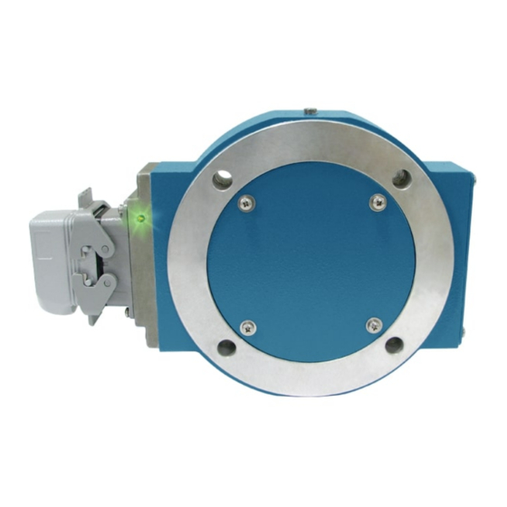
The Avtron Model AV850 SMARTach™ III is an incremental encoder
(also known as tachometer or rotary pulse generator), allowing operation
down to zero RPM. It provides a specific number of electrical Pulses Per
Revolution (PPR) that are proportional to a shaft's revolution. The AV850
SMARTach III is a bearingless, couplingless, modular design, providing
unequaled reliability and mechanical performance.
The AV850 fits AC and DC motors with an 8.5" C (FC / 180) Face. Both
end-of-shaft and through shaft mountings are accommodated.
The AV850 Encoder consists of three or four parts: a rotor, a stator
housing, and one or two removable sensor modules. No gapping,
adjustment, or shimming is required!
An Avtron AV850 SMARTach III is equipped with one or two AV5 sensor
modules. Each module has a two-phase output (A, B) 90° out of phase,
with complements (A, B), (A Quad B Output), and a marker pulse
with complement (Z, Z). For applications which require more than 2
independent outputs, AV850 encoders may be stacked via the use of
shaft adapters (see Table 2 for part numbers). Two separate encoders
would be purchased.
Output resolution on the AV850 is determined by the sensor only. Unlike
older models, any PPR's can be mixed and matched. Selection of the
rotor is based only on the shaft mounting requirements (and not PPR).
The AV5 removable sensor assembly has a diagnostic package that
includes Adaptive Electronics and a Fault-Check output. With this
package, the SMARTach III can maintain itself, and let you know if there
is a problem before the problem causes unscheduled downtime.
SECTION II: INSTALLATION
GENERAL
The motor must comply with NEMA MG1 for dimensions, face runout, and
shaft runout. Axial float or endplay must be less than +/-0.100" inch.
INSTALLATION HARDWARE
Installation hardware required is attached to each assembly.
Equipment needed for installation
Equipment Needed for Installation
Provided
Optional
AV850 Encoder
- A35226 Gauge or
A25355 M285/
- Washer, Spring Lock
AV850 Rotor
1/2 (4)
Gauge Block
- Hex Hd. Cap Screw
- Inboard Through-
1/2-13 x 3.00 (4)
Shaft Seal Plate
Rotor
- Outboard Through-
- Rotor Installation
Shaft Seal Plate Kit
Hardware Kit
- Silicone Lubricant
- Anti-Seize
or 20 Weight
Compound (copper)
Machine Oil
- Thread Locker (blue)
- Dead Blow Hammer
- Large Frame
Adapter Kit
(Modification "700")
AV850 Shield Kit
(A35355)
Model: AV850 SMARTach™ III
8-1/2" FC FACE MOUNT MODULAR
Not Provided
- 3/4" Wrench
- Phillips Screwdriver
- 7/16" Nut Driver
- Dial Indicator
- Vernier Caliper
- 3/32" Hex Wrench
(T-Handle style) (thru
shaft rotors only)
- 3/16" Hex Wrench
(cam screw rotors only)
- 9/16" Wrench (end-of-
shaft rotors only)
AV850
(OPTIONAL) LARGE MOTOR STATOR ADAPTER INSTALLATION
(Modification "700","704")
For large frame GE CD motors Avtron offers a frame adapter to add an
8.5" C-face to the motor. To install the flange adapter:
1. Remove all existing adapters on the non-drive end of the motor.
2. Clean the motor flange.
3. Using the supplied hardware, bolt the flange adapter in place
(see Figure 1).
4. Apply anti-seize to the frame adapter C-face flange.
(OPTIONAL) INBOARD SEAL PLATE INSTALLATION
(Cover Plate "B" & "N")
For installations where the AV850 will be mounted to an open frame
flange adapter, or other installation where the inner surface of the AV850
will not form a seal with the rear end bell of the motor, Avtron offers
inboard, through-shaft seal plate kits. These kits include a cover plate
and seal. See Table 3 for part numbers. To install the inboard through-
shaft seal plate kit:
1. Verify all components fit the motor shaft (rotor, V-ring seal, and
seal plate.
2. Slide V-ring seal onto motor shaft.
3. Apply a light coating of silicone lubricant or medium grade
machine oil to the outward face of the seal.
4. Use the seal plate to push the seal on the shaft; stop when the
seal plate contacts the motor face. Remove the seal plate and
push the V-ring seal an additional 0.09" [2.29mm] toward
motor.
Verify the V-ring seal is clear of the motor bearings and housing.
V-ring seal compression should be between 0.03" and 0.09"
[0.75mm-2.29mm] in final position when plate is reapplied.
5. Remove the double-stick tape protection. Align the bolt holes.
6. Stick the inner cover plate in place.
7. Mount rotor per instructions below, but increase axial position
from motor to rotor to 0.620" [15.75mm] (from 0.584") to
accommodate the inner seal plate thickness. See Figure 3.
8. Mount remainder of AV850 per instructions on next page.
MAGNETIC SHIELD INSTALLATION
For top performance on older motors with magnetized shafts and frames
install the AV850 shield. The AV850 also has built-in shields attached to
the housing of every unit. The standard AV850 shield as provided will
fit shafts up to 3" [76mm]. For larger shafts, if desired, the shield can
be custom-cut by the customer to fit a larger bore (recommend +0.125"
[3.1mm] over shaft size), or the shield can be omitted, as its effectiveness
is reduced beyond a 3" bore size.
NOTE
For additional magnetic field protection, consider the -004
option for extra sensor shielding.
1. Remove the double-stick tape protection.
2. Align the bolt holes and edges with the motor C-face.
3. Stick the shield in place on the motor C-face or on top of any
inboard seal plate.
4. Install rotor as usual, but gage location from the shield.
See Figure 3.
The outer edge of the rotor may be damaged by scratches, severe
blows, and strong magnetic fields.
1
Advertisement
Table of Contents

Related Manuals for Avtron SMARTach III AV850


Summary of Contents for Avtron SMARTach III AV850
-
Page 1: Section Ii: Installation General
An Avtron AV850 SMARTach III is equipped with one or two AV5 sensor will not form a seal with the rear end bell of the motor, Avtron offers modules. Each module has a two-phase output (A, B) 90° out of phase, inboard, through-shaft seal plate kits. - Page 2 TABLE 1 AV850 PART NUMBERS AND AVAILABLE OPTIONS Left Module Right Module Rotor Shaft Inboard & Outboard Connector Model Modifications Style Size Cover Plates Options Line Driver Line Driver AV850 X- none X- none X- none B- 480 2- 1500 X- none X- none B- 480...
-
Page 3: Rotor Installation
0.584” [14.83mm], as shown in Figure 2. Use Avtron gauges to 0.584”, as shown in Figure 2. Use Avtron gauges (A25355 or (A35226 or A25355) or housing alignment grooves as shown A35226) or use housing alignment grooves as shown in Figure in Figure 5 to verify position. -
Page 4: Troubleshooting
10. Note that this option does not ground the shield; test the wiring by replacing the AV5 sensor module. If the new module Avtron still recommends grounding the shield at the drive end of the shows GREEN, and the drive still shows encoder loss/tach fault, then cable for all wiring options. -
Page 5: Rotor Removal
Replace any magnetized material nearby with non-magnetic material (aluminum, stainless) (shafts, etc). For GE CD frame motors and similar styles, Avtron offers non-magnetic stub shafts (included with all “U” style rotor kits). If variations persist, consider replacing the sensors with super-shielded models, option -004. -
Page 6: Specifications
SPECIFICATIONS ELECTRICAL** LINE DRIVER OPTIONS A. Operating Power (Vin) LINE DRIVER OPTIONS 1. Volts ......5-24 VDC Electrical Specifications Units 2. Current ....100mA, nominal, no load B. Output Format Input Voltage 5-24 5-24 5-24 – – 1. 2O / & Comp ...A, A , B, B (differential line driver) –... -
Page 7: Wiring Diagrams
9388 6064 6 PAIR 9389 6066 * See Figure 7 page 6 for examples of alarm output wiring. ** Avtron recommends shield grounding at drive end . Shield pin does not ground the shield. EU Declaration of Conformity Labeled AV850... - Page 8 ALARM OUTPUT CONNECTION Avtron SMARTach III encoders provide an alarm signal if maintenance is required under specific circumstances. A green LED indicates power on and proper operation, red indicates alarm on. Following are application examples provided to help install the alarm output.
- Page 9 Table 3 SPARE END OF SHAFT ROTORS Motor Specific Style Universal Style Shaft Shaft Motor Frame Code Rotor Code Rotor Shaft Adapter** Magnetic Shield Grounding Kit Ground Kit Universal rotor only* -NA- -NA- -NA- B31515 none -NA- -NA- (no stub shaft) CD 180-32x EF/HF B30916-EF...
- Page 10 ADDITIONAL CONNECTOR OPTIONS FIGURE 8 1.42 0.312 (7.92) 5FT (1524.0) MIN (36.0) 4 Holes Terminal Block 0.53 OPTION "T" 1.16 (13.5) (29.3) Box is 3.12 (79.25) Deep OPTION "R" 2.00 4.31 (50.8) (109.5) OPTION "3" 6 PIN MS 1.16 CONNECTOR (29.3) (M940) 4.750 (120.6)
- Page 11 SMARTach™ III is a trademark of Nidec Industrial Solutions, Inc. Features and specifications subject to change without notice. Avtron Encoder standard warranty applies. All dimensions are in inches (mm). Avtron Encoders are the Most Reliable Encoders in the World REV DATE: 04/12/2022 Nidec Industrial Solutions 8901 E.
Need help?
Do you have a question about the SMARTach III AV850 and is the answer not in the manual?
Questions and answers