Advertisement
Quick Links
8 9 0 1 E . P L E A S A N T VA L L E Y R O A D • I N D E P E N D E N C E , O H I O 4 4 1 3 1 - 5 5 0 8
T E L E P H O N E : ( 1 ) 2 1 6 - 6 4 2 - 1 2 3 0 • F A X : ( 1 ) 2 1 6 - 6 4 2 - 6 0 3 7
E - M A I L : t a c h s @ a v t r o n - a i . c o m • W E B : w w w . a v t r o n e n c o d e r s . c o m
DESCRIPTION
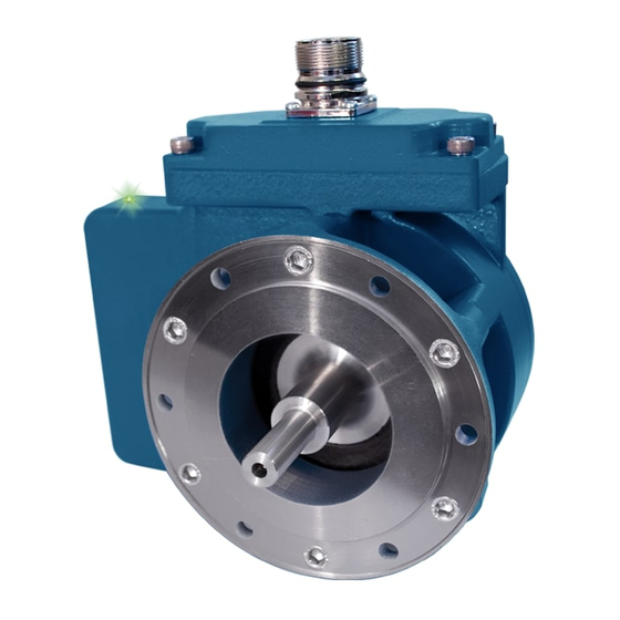
The Avtron Model AV45 is a heavy duty incremental encoder (also
known as tachometer or rotary pulse generator). Its output is directly
proportional to shaft position (pulse count) or speed (pulse rate). The
operates down to zero speed and
AV45
and instrumentation applications.
Do not utilize AV45 in hazardous locations which require
ATEX, UL, CUL, CSA, or other explosion protection cer-
tification. AV45 is not certified for hazardous locations.
Use XR models for hazardous applications.
AV45 PART NUMBERS AND AVAILABLE OPTIONS
Model
Shaft Size
AV45
N- 10mm
AF-60
H- 11mm, standard
AG-100
T- 18mm
AH-120
AA-128
AL-240
AN-256
AP-300
AE-360
AB-480
AQ-500
AR-512
AS-600
AV-900
AJ-960
AW-1000
AY-1024
AZ-1200
CX-1500
A3-2000
A4-2048
A5-2500
AD-4096
A8-4800
A9-5000
A0-Special
can be used for both control
CAUTION
Left
Right
Output
Output
Line Driver
PPR
PPR
XX-None
6- 5-24V in,
AF-60
5-24V out*
AG-100
AH-120
8- 5-24V in,
AA-128
5-15 out
AL-240
hi-power
AN-256
AP-300
9- 5-24V in,
AE-360
5V fixed out
AB-480
*Recommended
AQ-500
for single-ended
AR-512
applications
AS-600
AV-900
AJ-960
AW-1000
AY-1024
AZ-1200
CX-1500
A3-2000
A4-2048
A5-2500
AD-4096
A8-4800
A9-5000
A0-Special
Note Dual
Output NA
with Foot
Mount
Bracket
The AV45 is designed for mounting on European B10 style flanges
(85mm flange, 100mm bolt circle), or on a foot mount bracket for cou-
pling. The AV45 is not recommended for pulley or chain drive applica-
tions.
The AV45 utilizes magnetoresistive sensors. This proven technology
is ideal for rugged environments since it is immune to many contami-
nants that cause optical encoders to fail. All of the AV45 electronics
are potted, providing full protection against liquids. The outputs are
protected against short circuits and wiring errors.
Each AV45 has a two-phase output (A, B) 90° out of phase, with com-
–
–
plements (A
, B
), (A Quad B Output). A marker pulse with complement
–
(Z, Z
) is also present.
The AV45 has a diagnostic package that includes Adaptive Electronics
and a Fault-Check output and red/green LED for local indication. With
this package, the AV45 can maintain itself, and provide an alarm if
there is a problem before the problem causes un scheduled downtime.
Connector Options
Small EPIC Connector
P- Avtron pinout, w/mate
Terminal Box w/terminal strip
H- USA, 1/2" conduit
L- Europe w/cord grip
8 Pin M12 Connector
T- Global pinout, w/o plug
U- USA Pinout, w/o plug
12 Pin M23 Connector
2- Leine and Linde pinout, w/o plug
3- Hubner Pinout w/o plug
W- Cable 18" (or special length)
Encoder
Instructions
AV45
SOLID SHAFT
B10 FLANGE OR FOOT MOUNT
Foot Mount Bracket
Channels
X- None
A- All
-
- -
(for B10 flange mount)
A,B,A,B,Z,Z
(req'd for 8,
1- Toshiba TS2113N bolt
10 pin con-
pattern (recommend "T"
nectors)
18mm shaft)
B- A,B,A,B
(B35529 bracket)
2- POGxx, OGxx Hubner
(no marker)
(Baumer) bolt pattern
E- A,B,Z
(B35555 bracket)
3- FG4 Johannes Hubner
(single
ended)
bolt pattern
(B35338 bracket)
F- A,B
(single
ended, no
marker)
Modifications
000- None
004- Super
Magnetic
Shielding
6xx- Add over
speed switch
-
-
xx=speed
code
9xx- Specify cable
length xx=feet
max 33ft
(use w/ Option
"W")
Advertisement

Related Manuals for Avtron AV45 Series


Summary of Contents for Avtron AV45 Series
- Page 1 The AV45 is designed for mounting on European B10 style flanges (85mm flange, 100mm bolt circle), or on a foot mount bracket for cou- The Avtron Model AV45 is a heavy duty incremental encoder (also pling. The AV45 is not recommended for pulley or chain drive applica- known as tachometer or rotary pulse generator).
-
Page 2: Electrical Specifications
LINE DRIVER OPTIONS ELECTRICAL SPECIFICATIONS Electrical Specifications Units A. Operating Power (Vin) Input Voltage 5-24 5-24 5-24 1. Volts ......5-24 VDC in 2. Current ....... 100mA, each output, plus cable load Nom Output Voltage 5-24 5-15 B. Output Format –... - Page 3 Applies to Model AV45 Encoders connector styles “H”, “L”, “P”, “W” ALARM OUTPUT CONNECTION Avtron AV45 encoders provide an alarm signal if maintenance is required under specific circumstances. Following are application examples provided to help install the alarm output. Example 1. Alarm output using +V(OUT). +V(OUT) is equal to +V, the encoder power supply.
-
Page 4: Wiring Diagrams
WIRING DIAGRAMS CHANNELS CHANNELS CONNECTORS CHANNELS CONNECTOR CONNECTORS Avtron standard warranty applies. Copies available upon request. Specifications subject to change without notice. - Page 5 WIRING DIAGRAMS CHANNELS CONNECTORS CHANNELS CONNECTO Avtron standard warranty applies. Copies available upon request. Specifications subject to change without notice.
-
Page 6: Installation
Use thread locker supplied on cap components, refer to separate installation instructions in the Avtron screws which mount AV45 to foot bracket. PULSE GENERATOR HANDBOOK. -
Page 7: Troubleshooting
“alarm” output through the connector and connection on pin 10. Note that this option does as an integral LED. not ground the shield; Avtron still recommends TROUBLESHOOTING grounding the shield at the drive end of the cable for all wiring options. - Page 8 3.25 [82.6] 7.04 2.10 [178.8] [53.3] 4.53 [115.1] 4.53 3.35 3.94 [115.1] [85.0] [100.0] 6.52 [165.6] 0.26 [6.6] X 6 4.25 [108.0] Features and specifications subject to change without notice. Avtron standard warranty applies. All dimensions are in inches [mm].
- Page 9 [6.6] X 6 3.25 [82.6] 6.71 2.10 [170.4] [53.3] 8.50 4.53 3.35 3.94 [215.9] [115.1] [85.0] [100.0] 0.26 [6.6] X 6 4.24 [107.7] Features and specifications subject to change without notice. Avtron standard warranty applies. All dimensions are in inches [mm].
- Page 10 7.10 [180.3] 2.67 [70.0] 5.90 2.80 2.16 0.35 [149.9] [71.0] [54.9] [8.8] 4.72 [120.0] 0.71 0.47 [12.00] [18.00] 1.57 [40.0] 2.68 [68.0] Features and specifications subject to change without notice. Avtron standard warranty applies. All dimensions are in inches [mm].
- Page 11 [60.0] 1.73 [68.0] Features and specifications subject to change without notice. Avtron standard warranty applies. All dimensions are in inches [mm]. 8901 E. PLEASANT VALLEY RD., INDEPENDENCE, OH 44131, U.S.A. (1) 216-642-1230 • FAX (1) 216-642-6037 • www.avtronencoders.com REV: 07-25-12...
Need help?
Do you have a question about the AV45 Series and is the answer not in the manual?
Questions and answers