Table of Contents
Advertisement
Quick Links
8 9 0 1 E . P L E A S A N T VA L L E Y R O A D • I N D E P E N D E N C E , O H I O 4 4 1 3 1 - 5 5 0 8
T E L E P H O N E : ( 1 ) 2 1 6 - 6 4 2 - 1 2 3 0 • F A X : ( 1 ) 2 1 6 - 6 4 2 - 6 0 3 7
E - M A I L : t a c h s @ n i d e c - a v t r o n . c o m • W E B : w w w . a v t r o n e n c o d e r s . c o m
DESCRIPTION
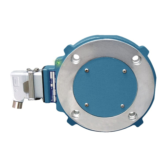
The Avtron Model XR125 SMARTSafe
encoder for hazardous locations (also known as tachometer or rotary
pulse generator), allowing operation down to zero RPM. It provides
a specific number of electrical Pulses Per Revolution (PPR) that are
proportional to a shaft's revolution. The XR125 SMARTSafe encoder
is a bearingless, couplingless, modular design, providing unequaled
reliability and mechanical performance.
CAUTION
The XR125 is designed for use in hazardous applications
which require protection from gas or dust ignition for
safe operation. Proper selection, wiring and installation
procedures are essential to ensuring safe conditions.
The XR125 fits AC and DC motors with an 12.5" C Face. Both end-of-
shaft and through shaft mountings are accommodated. XR125 may
also be installed as an open modular unit without the C Face.
The XR125 Encoder consists of three or four parts: a rotor, a stator
housing, and one or two removable sensor modules. These precision
machined parts mount to the accessory end of a motor that
conforms to NEMA MG1 for Type FC Face Mounting. See Mechanical
Specifications. No gapping, adjustment, or shimming is required!
(If the XR125 is installed as an open rotor and sensor only system
without a C face, then manual gapping of the sensor is needed.)
The XR125 utilizes magnetoresistive sensors. This proven technology
is ideal for rugged environments since it is immune to many
contaminants that cause optical encoders to fail. All of the XR125
electronics are potted, providing full protection against liquids.
The outputs are protected against short circuits and wiring errors.
An Avtron XR125 SMARTSafe encoder has a two-phase output (A,B)
90° out of phase, with complements (A
marker pulse with complement (Z, Z
Because the XR125 is modular, there are no bearings or couplings
required. This, combined with the latest magneto resistive (MR)
sensor technology, allows the XR125 to provide superior mechanical
performance and increased reliability.
Output resolution on the XR125 is determined by the sensor only.
Unlike older models, any PPRs can be mixed and matched. Selection
of the rotor is based only on the shaft mounting requirements (and not
PPR).
ADAPTIVE ELECTRONICS
A perfect duty cycle consists of a waveform whose "high" and
"low" conditions are of the same duration (50%/50%). It is possible
over time for the duty cycle and edge separation to change due to
component drift, temperature changes, or mechanical wear. The
Adaptive Electronics extend the life of the XR125 by constantly
monitoring and correcting duty cycle and edge separation over time.
encoder is a heavy duty
TM
–
–
, B
), (A Quad B Output), and a
–
).
The XR125 has been evaluated to be compliant with IEC60079-
0:2007, IEC60079-11:2011, EN60079-0:2009, EN60079-11:2012,
BSEN 61000-6-4:2007 and BSEN61000-6-2:2005 (Certificates of
conformity: TRAC12ATEX0002X, TRAC12ATEX 0003X, IECEx TRC
12.0009X, and IECEx TRC12.0001X.)
THE XR125 IS CERTIFIED FOR USE IN:
Group II, Category 2 (ATEX Zone 1), Gas Group IIC potentially
explosive atmospheres when marked CE 0539
IIC T4 Gb -40°C < Tamb < 80°C and used with an Avtron isolator
marked CE 0539
Ex
Group II, Category 2 (ATEX Zone 21), Dust Group IIIC potentially
explosive atmospheres when marked CE 0539
IIIC T200°C Db -40°C<Tamb<80°C and used with an Avtron isolator
marked CE 0539
Ex
Group II, Category 3 (ATEX Zone 2), Gas Group II_* potentially
explosive atmospheres when marked CE
T4 -40°C<Tamb<80°C
*see chart in specification section and used with a power supply
that limits voltage and current per the chart in the specification
section.
Group II, Category 3 (ATEX Zone 22), Dust group IIIC potentially
explosive atmospheres when marked CE
200°C Dc -40°C<Tamb<80°C.
See installation section for electrostatic charging hazard instructions
and other limitations.
INSTALLATION
WARNING
Installation should be performed only by qualified
personnel. Safety precautions must be taken to ensure
machinery cannot rotate and all sources of power are
removed during installation.
Equipment Group II, Category 2 (Zone 1), Gas group IIC, Dust
group IIIC (ATEX Zone 21): Available as a system only including
XR125 with line driver option 5 and an Avtron Isolator module XRB1
(P/N B35134).
System parameters are:
Um= 250V
Uo (open circuit voltage) = 7.14VDC max.
Io (short circuit current) = 420mA max.
Co (system capacitance) = 13.5uF max.
Lo (system inductance) = 0.15mH max.
Encoder parameters are:
Ui (input voltage) = 7.14VDC max.
Ii (fault current) = 420mA max.
Ci (internal capacitance) = 11.9uF max.
Li (internal inductance) = 0mH max.
XR125
1
ATEX Instructions
MODEL
XR125
12.5" FACE MOUNT
MODULAR FOR HAZARDOUS
APPLICATIONS
II 2 GD, Ex ib
Ex
[II 2 GD] [Ex ib IIC Gb] -40°C<Tamb<80°C.
II 2 GD, Ex ib
Ex
[II 2 GD] [Ex ib IIIC Db] -40°C<Tamb<80°C .
II 3 GD, Ex ic IIC* Gc
Ex
II 3 GD, Ex ic IIIC T
Ex
Advertisement
Table of Contents

Subscribe to Our Youtube Channel
Related Manuals for Avtron SMARTSafe XR125


Summary of Contents for Avtron SMARTSafe XR125
- Page 1 CE 0539 II 2 GD, Ex ib IIC T4 Gb -40°C < Tamb < 80°C and used with an Avtron isolator CAUTION marked CE 0539 [II 2 GD] [Ex ib IIC Gb] -40°C<Tamb<80°C.
-
Page 2: Installation Hardware
[27.9mm]. The innermost surface of the rotor will be 0.584” GENERAL from the motor c-face, as shown in Figures 2 & 3. Use Avtron The motor must comply with NEMA MG1 for dimensions, face gauges (A35679 or A25355) or housing alignment grooves as runout, and shaft runout. -
Page 3: Maintenance
For applications requiring shafts to pass completely through the or jog mode of the speed controller. XR125, Avtron offers an outboard through-shaft seal plate kit with V-ring seal. See Table 3 for part numbers and Figure 3. Note that Interconnection cables specified in the wire selection chart are for large through-shaft bores T8 and T9, no seal is available. -
Page 4: Rotor Removal
Replace any magnetized material nearby with non-magnetic material (aluminum, stainless) (shafts, etc). For GE CD frame motors and similar styles, Avtron offers non-magnetic stub shafts (included with all “U” style rotor kits). If variations persist, consider replacing the sensors with super-shielded models, option -004. - Page 5 XR125 PART NUMBERS AND AVAILABLE OPTIONS Inboard & Left Module Right Module Thru Shaft Rotor Bore, Connector Model Outboard Modifications US Sizes Options Line Driver Line Driver Cover Plates XR125 X- none 5- Zone 1 & 21 X- none 000-none XX- no T4- 3.875"...
- Page 6 SPECIFICATIONS ELECTRICAL LINE DRIVER OPTIONS A. Operating Power (Vin) LINE DRIVER OPTIONS 1. Volts ......See Line Driver Option Chart 2. Current ......100mA, each output, no load Electrical Specifications Isolator XRB1 Units B. Output Format Input Voltage 5-24 12-24 1. 2O/ & Comp ....A, , B, (differential line driver) 2.
- Page 7 SPARE MECHANICAL PARTS FOR AV125 Through Shaft Rotors Outboard Covers Shaft Bore Set Screw Flat Thru-Shaft Cover Seal ONLY Imperial (US) Sizes Rotor Code Rotor Part 1.375" B31204-TH A35681 A34376-1 471884 1.625" B31204-TJ A35681 A34376-2 471901 1.875" B31204-TL A35681 A34376-3 471902 2.000"...
-
Page 8: Wiring Diagrams
Phasing Signal from the back of the Encoder Gnd A+ B+ Z+ Alm+ +Vin Code Code 10 Pin MS Avtron / on 12” Cable Pin # Phasing is defined as the direction of 10 Pin MS Mini Twist Lock R, S... - Page 9 WIRING DIAGRAMS ZONE 2 HAZARDOUS AREA DIFFERENTIAL 2 PHASE WIRING SAFE AREA 5-24 Volts Out Belden Alpha Typical Cable 500'(150M)max 2 Pair 9552 2242C 3 Pair 9553 2243C 18AWG, Twisted Pair + Overall Shield ENCODER LINE 4 Pair 9554 2244C 5 Pair 2245C 1328A...
-
Page 10: Alarm Output Connection
ALARM OUTPUT CONNECTION Avtron THIN-LINE II encoders provide an alarm signal if maintenance is required under specific circumstances. An alarm LED indicator is also available. Green indicates power on, red indicates alarm on. Following are application examples provided to help install the alarm output. - Page 11 OPTIONAL OUTBOARD ROTOR MOUNTING SEAL PLATE (Through Shaft Shown) 1.097" +/-0.100" 1.097" +/-0.100" [27.9mm +/-2.5mm] [27.9mm +/-2.5mm] 0.584" +/-0.100" [14.8mm +/-2.5mm] 0.584" +/-0.100" V-RING [14.8mm +/-2.5mm] SEAL MOTOR MOTOR SHAFT MOTOR “A” SET SCREW STYLE “TA-T9, MA-M9” ACCESSORY MOUNTING FACE ROTOR ALIGNMENT GROOVE “A”...
-
Page 12: Outline Drawing
Authorized Company Representative Title Date Features and specifications subject to change without notice. Avtron standard warranty applies. All dimensions are in millimeters approx. REV: 03/25/13 8901 E. PLEASANT VALLEY RD., INDEPENDENCE, OH 44131, U.S.A. (1) 216-642-1230 • FAX (1) 216-642-6037 • www.avtronencoders.com...
Need help?
Do you have a question about the SMARTSafe XR125 and is the answer not in the manual?
Questions and answers