Table of Contents
Advertisement
Quick Links
Nidec-Avtron Makes the Most Reliable Encoders in the World
8 9 0 1 E . P L E A S A N T VA L L E Y R O A D • I N D E P E N D E N C E , O H I O 4 4 1 3 1 - 5 5 0 8
T E L E P H O N E : ( 1 ) 2 1 6 - 6 4 2 - 1 2 3 0 • F A X : ( 1 ) 2 1 6 - 6 4 2 - 6 0 3 7
E - M A I L : t a c h s @ n i d e c - a v t r o n . c o m • W E B : w w w . a v t r o n e n c o d e r s . c o m
DESCRIPTION
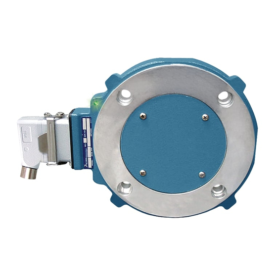
The Avtron AV85 is a modular, two piece incremental encoder (also
known as a tachometer or rotary pulse generator). It provides a two
phase, A Quad B frequency (pulse) output, with complements. The
AV85 mounts on a 8.5" (NEMA FC) Face.
Because the AV85 is modular, there are no bearings or
couplings required. This, combined with the latest magneto
resistive (MR) sensor technology, allows the AV85 to provide superior
mechanical performance and increased reliability. An Avtron AV85 can
be configured with one or two independent outputs. Each output has
six signals: (A, B) 90° out of phase, with complements (A, B). A marker
pulse with complement (Z, Z) is also provided.
Output resolution on the AV85 is determined by the sensor only. Unlike
older models, any PPRs can be mixed and matched. Selection of the
rotor is based only on the shaft mounting requirements (and not PPR).
AV85 PART NUMBERS AND AVAILABLE OPTIONS
Shaft Size
Model Housing Type
(Thru Shaft Rotor)
AV85A
1- Single Output
C0- Non-std. Shaft Size
XX- None
2- Dual Output
Thru Shaft Rotor
US
CA- 0.500
CB- 0.625
CC- 0.875
CD- 0.938
CE- 1.000
CF- 1.125
CG- 1.250
CH- 1.375
CT- 1.500
CJ- 1.625
*
Set Screw Rotor only
CK- 1.750
CL- 1.875
CM- 2.000
CN- 2.125
CQ- 2.250
CP- 2.375
CR- 2.500
TS- 2.625*
TU- 2.875*
TW- 2.750*
TV- 3.000*
T4- 3.125*
T7- 3.188*
TZ- 3.250*
Mounted on Encoder
10 Pin
10 Pin MS
EPIC
A- w/o plug (std. phasing)
G- w/ plug
B- w/o plug (Dynapar
Northstar
HS35 phasing)
pinout
C- "A" w/ plug
P- w/ plug
D- "B" w/ plug
Cover Style Line Driver
E- Extended
6- 5-24V in/out
Shaft Cover
8- 5-24 V in,
F- Flat Cover
5-24 V out
Metric
T- Flat Thru-
high power
D2- 10mm
Hole Cover with
9- 5-24V in,
DA- 11mm
Shaft Seal
5V out
D3- 12mm
DB- 14mm
D- Dome Cover
DC- 15mm
DD- 16mm
D4- 18mm
DE- 19mm
DF- 24mm
DG- 28mm
DH- 30mm
DT- 32mm
DJ- 36mm
DK- 38mm
DL- 42mm
DM- 45mm
DN- 48mm
DP- 52mm
DR- 55mm
DS- 60mm
MU- 65mm*
MV- 70mm*
MW- 75mm*
MY- 80mm*
MZ- 85mm*
Connector Options
Mounted on Flex cable
7 Pin
10 Pin
10 Pin
«
«
mini MS
MS
MS
R- w/
J- w/o
Y- 12"
Q- 18"
plug
plug
cable w/o
cable w/o
plug on
plug on
conduit box
remote
(Large
mount
Encoder
blade
Pinout)
Z- 36"
cable w/
plug
Equipment Needed for Installation
Provided
AV85 Stator/Housing
Socket Hd Cap Screw
1/2"-13 x 1.50" (4)
AV85 Rotor
Socket Set Screw
#M4 x 8mm (2) or Pre-
Installed Cam Screw or
End-of-Shaft w/
screws:
CD 180-320 3/8"-16
x1" + pin
CD360 10-24 x 0.5" (2)
CD400, 500 3/8"-16 x
0.88" (2)
Thread locker (blue)
Single/Left
Right Output
Output (PPR)
(PPR)
0- Non-
S- 600
0- Non-
S- 600
std.
V- 900
std.
V- 900
F- 60
J- 960
F- 60
J- 960
G- 100
W- 1000
G- 100
W- 1000
H- 120
Y- 1024
H- 120
Y- 1024
A- 128
Z- 1200
A- 128
Z- 1200
3- 2000
3- 2000
L- 240
L- 240
4- 2048
4- 2048
N- 256
N- 256
5- 2500
5- 2500
P- 300
P- 300
E- 360
D- 4096
E- 360
D- 4096
B- 480
8- 4800
B- 480
8- 4800
Q- 500
9- 5000
Q- 500
9- 5000
R- 512
R- 512
X- None
10 Pin
10 Pin
«
«
EPIC
mini MS
S- 18"
cable w/
plug
AV85
1
Encoder
Instructions
MODEL
AV85
8 1/2" C-Face MOUNT
MODULAR
Optional
Not Provided
Extended Shaft
Phillips Screwdriver
Cover w/ Screws
2mm Hex Wrench
6-32 x 0.31" (4)
(T-Handle
Flat Cover w/Screws
Style for Large-bore Thru-
10-24 x 0.38" (4)
Shaft Rotors)
Lock Washers
3mm Hex Wrench
Thru Shaft Cover
(T-Handle
w/ Screws 10-24 x
Style for Cam Screw
0.38" (4)
Rotors)
w/ V-Ring Seal and
3/8" Hex Wrench (T-Handle
Silicone Lubricant
Style for Stator/Housing)
End-of-Shaft ONLY
5/32" Hex Wrench
5/16" Hex Wrench
9/16" Wrench
Connector
Modifications
W- 3ft. Cable, Sealed
000- No Modification
004- Add Housing Drain
(single output only)
005- Super Magnetic Shielding
4xx- Special PPR
Enter Ø in the PPR
code(s), select the special
option code below
9xx- Special Cable Length,
xx=length in feet
SPECIAL PPR OPTION CODES
OPTION
LEFT
CODE
PPR
401
402
403
404
405
406
407
408
409
410
RIGHT
PPR
1270
None
150
None
50
None
512
16
16
None
6000
None
2800
None
1400
None
30
None
None
6000
Advertisement
Table of Contents

Related Manuals for Avtron AV85


Summary of Contents for Avtron AV85
- Page 1 Rotors) w/ V-Ring Seal and CD 180-320 3/8"-16 Output resolution on the AV85 is determined by the sensor only. Unlike 3/8" Hex Wrench (T-Handle Silicone Lubricant x1" + pin older models, any PPRs can be mixed and matched. Selection of the Style for Stator/Housing) CD360 10-24 x 0.5"...
-
Page 2: Installation
Installation and removal videos for the AV56/67/85/115 are available the rotor bore before mounting. Tighten the rotor set screws to 15 inlb on Avtron’s web site. Refer to the back page of these instructions for [2 Nm] using the 2mm Thandle hex wrench. - Page 3 LED shows GREEN, then check the wiring between the drive and the encoder. If the wiring appears correct and in good shape, test the wiring by replacing the AV85. If the new unit shows GREEN, and the drive still shows encoder loss/tach fault, then the wiring is faulty and should be repaired or replaced.
- Page 4 Remove the AV85 from the motor. Clean the housing mounting Disengage the (2) cam screws or endofshaft mounting screw(s) by surface for the AV85 housing. Ensure the AV85 is directly mounted on turning them counterclockwise less than 1 full turn. The cam heads the motor, with no sealant, gasketing, or other materials, and is firmly will visibly move away from the shaft.
- Page 5 0.87"-1.38" [22.2-34.9] 0.24" ± 0.03" [6.1±0.8] 0.27" [6.9] MIN 1.50"- 2.63" [38.1-66.7] 0.31" [7.9] MIN 0.28" ± 0.04" [7.1±1.0] MOTOR 2.75"- 3.00" [70.0-79.4] 0.35" ± 0.05" [8.9±1.3] 0.38" [9.7] MIN >3.00 [>75mm] 0.38" [9.7] MIN 0.35" ± 0.05" [8.9 ±1.3] AV85...
- Page 6 THIN-LINE II & III Spare Parts (AV56/AV67/AV85/AV115 Only) SAE/USA Sizes Rotors AV56A, AV67, Thru-Shaft Covers AV85, AV115 Shaft AV56,AV67 & Size Option AV85 Set Screw AV115 Cover Seal Only Code Screw Cover /kit .500/.4995 AVTR1-CA A36521-TA A36523-TA 471960 .625/.6245 AVTR1-CB...
- Page 7 THIN-LINE II & III Spare Parts (AV56/AV56S/AV67/AV85/AV115 Only) Metric Sizes Rotors AV56A, AV67, Thru-Shaft Covers AV85, AV115 Shaft AV56, AV56S, Size Option AV85 Set Screw AV67 & AV115 Seal Only Code Screw Cover /kit Cover Kit 10mm AVTR1-D2 A36522-M2 A36524-M2...
-
Page 8: Wiring Diagrams
For option “W”, unused outputs must be insulated to prevent BELDEN ALPHA accidental contact. 2 PAIR 9368 5620B1802 NOTE: Avtron standard 3 year warranty applies. Copies available 3 PAIR 9773 or 9369 6445 upon request. Specifications subject to change without notice. 4 PAIR 9388... -
Page 9: Application Examples
THIN-LINE II™ and III™ Application Examples Applies to all AV85 models, except, wiring options “A”, “B”, “C”, “D”, “G”, “Q”, “R”, “S”, “T” and “U”. ALARM OUTPUT CONNECTION Avtron THIN-LINE II & III encoders provide an alarm signal if maintenance is required under specific circumstances. An alarm LED indicator is also available. -
Page 10: Outline Drawing
1 – WEIGHT: 2.5 - 4LBS [1.13 TO 1.81 KG]. NOTES: Features and specifications subject to change without notice. Avtron standard warranty applies. All dimensions are in millimeters approx. THINE-LINE , THIN-LINE II and THIN-LINE III are trademarks of Nidec-Avtron.
Need help?
Do you have a question about the AV85 and is the answer not in the manual?
Questions and answers