Advertisement
Quick Links
Nidec-Avtron Makes the Most Reliable Encoders in the World
8 9 0 1 E . P L E A S A N T VA L L E Y R O A D • I N D E P E N D E N C E , O H I O 4 4 1 3 1 - 5 5 0 8
T E L E P H O N E : ( 1 ) 2 1 6 - 6 4 2 - 1 2 3 0 • F A X : ( 1 ) 2 1 6 - 6 4 2 - 6 0 3 7
E - M A I L : t a c h s @ n i d e c - a v t r o n . c o m • W E B : w w w . a v t r o n e n c o d e r s . c o m
DESCRIPTION
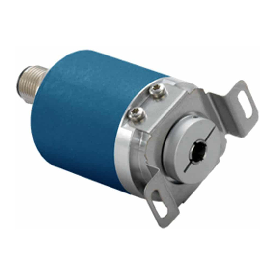
The Avtron Model HS6M is a light mill duty absolute encoder. It
expresses the position of rotation as an output message or value.
HS6M can measure a single turn of rotation or multiple rotations.
The HS6M measures the shaft rotation and position without the need
for external power or internal batteries or capacitors through its
innovative Wiegand wire energy system. The HS6M operates down
to zero speed and can be used for both control and instrumentation
applications.
CAUTION
Do not utilize HS6M in hazardous locations which
require ATEX, UL, CUL, CSA, or other explosion protection
certification. AV6M is not certified for hazardous
locations.
When mounted to a machine shaft, the HS6M design eliminates the
need for shaft couplings, adapter flanges, or accessory mounting
faces. The clamping collar holds the HS6M in place.
For larger bore/ larger frame size units, shaft inserts are available
to resize from native bores to smaller sizes. An anti-rotation arm
prevents housing rotation while allowing for shaft end float.
HS6M PART NUMBERS AND AVAILABLE OPTIONS
Model
Bus
Housing
HS6M
A- Analog
1- 58mm
C- CANOpen
3- 36.5mm
D- DeviceNet
7- 42mm
J- J1939
S- SSI
HOUSING COMPATIBILITY
Housing
Bore Size
1
M, N, P, R, Z
3
7
M, N, P
Turns/
Bore Size
bits
L- 6mm
X- 0/0-
single turn
M- 8mm
A- 16/4
N- 10mm
(analog)
P- 12mm
2- 4096/12
R- 15mm
3- 8192/13
Z- All metric
5- 32768/15
sizes
IP/Sealing
A, K
L
X, A
A
The HS6M utilizes magnetic sensors. This proven technology is ideal
for rugged environments since it is immune to many contaminants
that cause optical encoders to fail.
SAFETY
The HS6M is not considered as a safety device and is not suitable for
connection into a safety system.
CAUTION
Be careful not to damage clamping fingers of hollow
shaft during handling. Do not tighten clamping collar
before installation onto motor shaft.
WARNING
Installation should be performed only by qualified
personnel. Safety precautions must be taken to ensure
machinery cannot rotate and all sources of power are
removed during installation.
INSTALLATION
Refer to the back page of these instructions for outline and mounting
dimensions.
PPR/bits
Mounting
Connector
per turn
Style
2- 4096/12*
A- 1xM12/5 pin
E- EOS only
3- 8192/13
C- M12 x3 pin
E- 1xM12/8 pin
*use '2' also for
analog output
F- M23/12 pin
K- 3x cable entry
W- Cable, 1m
STANDARD CONNECTORS & OUTPUT FORMATS
Bus
Code
Analog
CANOpen
DeviceNet
J1939
SSI
HS6M
1
Encoder Instructions
MODEL
HS6M
HOLLOW SHAFT 6-15mm
IP
Output
Rating
Digital
X- no shaft seal,
IP54, aluminum
1- Binary
+ steel housing
2- Gray
A- IP65 seals,
Analog
aluminum + steel
housing
3- V output
K- IP69K stainless
0-5V
housing
4- V output
0-10V
5- I Output
4-20mA
6- I Output
0-20mA
Connectors
Output
A
A, W
3, 4, 5, 6
C
A, W
1
D
A, W
1
J
A, W
1
S
E, F, W
1, 2
Special
Option
000- none
9xx- special
cable
length
xx=length
*0.3m
001- pushbutton
setpoints
Advertisement

Related Manuals for Avtron HS6M


Summary of Contents for Avtron HS6M
- Page 1 SAFETY The HS6M measures the shaft rotation and position without the need The HS6M is not considered as a safety device and is not suitable for for external power or internal batteries or capacitors through its connection into a safety system.
-
Page 2: Environmental Considerations
Equipment needed for installation REPLACING PARTS Supplied: HS6M Encoder The HS6M has two items that are user-replacable in the field in case of damage, or to change the encoder electrical or mechanical Anti-Rotation Tether interface: Shaft sizing insert: Simply slide the insert out of the HS6M and Optional: replace it with the new bore size insert. - Page 3 Flashes - Software download in progress ON - Encoder is operating normally with no errors Nidec-Avtron recommends the use of a simple no-cost debugging tool such as PCAN View. Ensure the device is set to the proper baud rate (connection cap, or...
- Page 4 Protection Short Circuit Transient All cable lengths shown with optimal cable and minimum supported baud rate: SSI: @100kbaud w/24 AWG, 52.5 pF/meter (16 pF/foot) DeviceNet: Using main cable (round, large diameter) CANOpen: @20kbaud Profibus DP: 9.6Kbaud, 150ohm cable, <10pf/ft HS6M...
- Page 5 For input logic zero or no connection, the encoder will count UP for CCW rotation as viewed from the rear end of the encoder. For input logic 1 (>10V, <Vs), the encoder will count DOWN for CCW rotation as viewed from the rear of the encoder. HS6M...
- Page 6 0x01 for units with connection cap including hardware node and baud rate selection. (software commands will not change node) Nidec-Avtron recommends the use of a simple no-cost debugging 0x20 is the factory default for units with software-selectable tool such as PCAN View.
- Page 7 ID: 0x620 0x22 0x00 0x23 0x00 0x55 0xAA 0xAA 0x55 No reset is triggered. Cycle power after saving changes to parameters. Other Parameters Contact Nidec Avtron for additional parameters, diagnostic registers, cam and programmable limit switch functionality and other advanced features. HS6M...
- Page 8 Other Parameters For more details on DeviceNet, consult the Open DeviceNet Vendor’s Association (ODVA): Contact Nidec-Avtron or review the EDS file for additional parameters, diagnostic registers, cam and programmable limit www.odva.org switch functionality and other advanced features.
- Page 9 Profibus DP is typically a master-slave network-the master/scanner lowest 13 bits = position within one turn, next 12 bits (up to bit 25) device gathers data from each (slave) device on the bus. Avtron represent turns position data. Setting Zero Position for Multiturn Encoders and Single turn encoders are Profibus DP slave devices.
- Page 10 HS6M WIRING DIAGRAMS Communication Bus “A”: Analog Pinout OPTION OPTION “S” CONNECTOR “W” (1x Cable (Cable) Entry) SIGNAL SIGNAL BLACK Set Upper End Point 2 WHITE Set Upper End Point 2 Set Lower End Point 1 BROWN Set Lower End Point 1...
- Page 11 HS6M WIRING DIAGRAMS Communication Bus “P”: Profibus Pinout OPTION OPTION CONNECTOR “C” “K” M12x3 (3x cable) SIGNAL CONNECTOR Terminal Point SIGNAL GND (0V) Any (-) GND (OV) 4 pin male Any (+) Bus A in Leftmost A Bus A out...
- Page 12 HS6M WIRING DIAGRAMS CANOpen Bus “C” OPTION OPTION “A” “W” (M12 / 5 (Cable) pin) SIGNAL CAN_GND GREEN CAN_GND CAN_V+ CAN_V+ CAN_H WHITE CAN_H CAN_L BROWN CAN_L YELLOW * NOTE: Twisted pair cable required with individual and overall shields. Obey pairing as shown.
- Page 13 HS6M, 36.5mm Housing “3”, Connector/Cable “W” 6mm bore “L”, IP54 Seals & Aluminum+Steel Enclosure “X” All dimensions are in mm [inches] approx. HS6M...
- Page 14 HS6M, 36.5mm Housing “3”, Connector M12 “A”,”E” 6mm bore “L”, IP65 Seals & Aluminum+Steel Enclosure “A” All dimensions are in mm [inches] approx. HS6M...
- Page 15 HS6M, 42mm Housing “7”, Connector M12, “A”, “E” 12mm bore “P”, IP65 Seals & Aluminum+Steel Enclosure “A” All dimensions are in mm [inches] approx. HS6M...
- Page 16 15mm bore “R”, IP65 Seals & Aluminum+Steel Enclosure “A” Features and specifications subject to change without notice. Avtron standard warranty applies. All dimensions are in mm [inches] approx. NIDEC AVTRON AUTOMATION CORPORATION 8901 E. PLEASANT VALLEY RD., INDEPENDENCE, OH 44131, U.S.A.
Need help?
Do you have a question about the HS6M and is the answer not in the manual?
Questions and answers