Table of Contents
Advertisement
Quick Links
Nidec-Avtron Makes the Most Reliable Encoders in the World
8 9 0 1 E . P L E A S A N T VA L L E Y R O A D • I N D E P E N D E N C E , O H I O 4 4 1 3 1 - 5 5 0 8
T E L E P H O N E : ( 1 ) 2 1 6 - 6 4 2 - 1 2 3 0 • F A X : ( 1 ) 2 1 6 - 6 4 2 - 6 0 3 7
E - M A I L : t a c h s @ n i d e c - a v t r o n . c o m • W E B : w w w . a v t r o n e n c o d e r s . c o m
DESCRIPTION
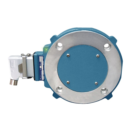
The Avtron XR56, SMARTSafe™ is a modular, two piece incremental
encoder for hazardous atmosphere applications (also known as a
tachometer or rotary pulse generator). It provides a two phase, A Quad
B frequency (pulse) output, with complements. The XR56 mounts on a
4.5" (NEMA 56C) Face.
CAUTION
The XR56 is designed for use in hazardous applications
which require protection from gas or dust ignition for
safe operation. Proper selection, wiring and installation
procedures are essential to ensuring safe conditions.
Because the XR56 is modular, there are no bearings or couplings
required. This, combined with the latest magneto resistive (MR)
sensor technology, allows the XR56 to provide superior mechanical
performance and increased reliability.
An Avtron XR56 can be configured with one or two independent
outputs. Each output has six signals: (A, B) 90° out of phase, with
–
–
complements (A
, B
). A marker pulse with complement (Z, Z
provided.
Output resolution on the XR56 is determined by the sensor only.
Unlike older models, any PPRs can be mixed and matched. Selection
of the rotor is based only on the shaft mounting requirements (and not
PPR).
ADAPTIVE ELECTRONICS
A perfect duty cycle consists of a waveform whose "high" and
"low" conditions are of the same duration (50%/50%). It is possible
over time for the duty cycle and edge separation to change due
to component drift, temperature changes, or mechanical wear.
The Adaptive Electronics extend the life of the XR56 by constantly
monitoring and correcting duty cycle and edge separation over time.
The XR56 has been evaluated to be compliant with IEC60079-0:2007,
IEC60079-11:2011, EN60079-0:2009, EN60079-11:2012,
BSEN 61000-6-4:2007 and BSEN61000-6-2:2005 (Certificates of
conformity: TRAC12ATEX0002X, TRAC12ATEX 0003X, IECEx TRC
12.0009X, and IECEx TRC12.0001X.)
THE XR56 IS CERTIFIED FOR USE IN:
Group II, Category 2 (ATEX/IECEx Zone 1), Gas Group IIC
potentially explosive atmospheres when marked CE 0539
Ex ib IIC T4 Gb -40°C < Tamb < 80°C and used with an Avtron isolator
marked CE 0539
[II 2 GD] [Ex ib IIC Gb] -40°C<Tamb<80°C.
Ex
Group II, Category 2 (ATEX/IECEx Zone 21), Dust Group IIIC
potentially explosive atmospheres when marked CE 0539
II 2 GD, Ex ib IIIC T200°C Db -40°C<Tamb<80°C and used with
an Avtron isolator marked CE 0539
-40°C<Tamb<80°C .
Group II, Category 3 (ATEX/IECEx Zone 2), Gas Group II
* potentially explosive atmospheres when marked CE
Ex ic IIC* Gc T4 -40°C<Tamb<80°C
*see chart in specification section and used with a power supply that
limits voltage and current per the chart in the specification section.
–
) is also
II 2 GD,
Ex
Ex
[II 2 GD] [Ex ib IIIC Db]
Ex
II 3 GD,
Ex
XR56
ATEX/IECEx Instructions
XR56
MODULAR FOR HAZARDOUS
Group II, Category 3 (ATEX/IECEx Zone 22), Dust group IIIC
potentially explosive atmospheres when marked CE
IIIC T 200°C Dc -40°C<Tamb<80°C.
See installation section for electrostatic charging hazard instructions
and other limitations.
INSTALLATION
WARNING
Installation should be performed only by qualified
personnel. Safety precautions must be taken to ensure
machinery cannot rotate and all sources of power are
removed during installation.
Equipment Group II, Category 2 (ATEX/IECEx Zone 1), Gas group
IIC, Dust group IIIC (ATEX/IECEx Zone 21): Available as a system
only including XR56 with line driver option 5 and an Avtron Isolator
module XRB1 (P/N B35134).
System parameters are:
Um= 250V
Uo (open circuit voltage) = 7.14VDC max.
Io (short circuit current) = 420mA max.
Co (system capacitance) = 13.5uF max.
Lo (system inductance) = 0.15mH max.
Encoder parameters are:
Ui (input voltage) = 7.14VDC max.
Ii (fault current) = 420mA max.
Ci (internal capacitance) = 11.9uF max.
Li (internal inductance) = 0mH max.
The isolator XRB1 can be supplied as a separate module for location
in a safe area or in an explosion proof box on a short flexible cable
tethered to the encoder.
Equipment Group II, Category 3 (ATEX/IECEx Zone 2), Gas group
IIC, Dust group IIIC (ATEX/IECEx Zone 22): Requires an XR56 with
line driver option 7 and a SELV (Energy Limited) or equivalent power
supply which limits voltage and current to the values in the table in
the specifications. If current limit is not inherent in the power supply a
separate fuse between the power supply and encoder can be used to
limit current.
NOTE:
Isolators, encoders and cable must be selected and
installed in accordance with the latest edition of
IEC/EN60079-14 and IEC/EN60079-25. Cable
characteristics must comply with IEC/EN60079-14 and
IEC/EN60079-25 and for zone 1 applications total
system capacitance between the isolator and encoder
(including cable) must be less than Co-Ci. Total system
inductance between the isolator and encoder must be
less than Lo-Li.
The equipment is intended for a fixed installation and
should be mounted so as to avoid electrostatic charging.
The XR56 is not considered as a safety device and is not
suitable for connection into a safety system.
1
SMARTSafe
™
4 1/2" C-FACE MOUNT
APPLICATIONS
II 3 GD, Ex ic
Ex
Advertisement
Table of Contents

Related Manuals for Avtron XR56 SMARTSafe


Summary of Contents for Avtron XR56 SMARTSafe
- Page 1 CE 0539 II 2 GD, NOTE: Ex ib IIC T4 Gb -40°C < Tamb < 80°C and used with an Avtron isolator Isolators, encoders and cable must be selected and marked CE 0539 [II 2 GD] [Ex ib IIC Gb] -40°C<Tamb<80°C.
- Page 2 The XR56 installation is similar to AV56. Installation and removal Covers must not interfere with the motor shaft or rotor. The longest videos for the AV56/67/85/115 are available on Avtron’s web site. shaft that can be used without interfering is 0.72” [18.3mm] with a Refer to the back page of these instructions for outline and mounting standard flat cover (Cover Style option “F”) and 2.55”...
- Page 3 (aluminum, stainless) (especially shafts). For GE a) Single Ended 2 Phase Wiring (see wiring diagram) CD frame motors and similar styles, Avtron offers non-magnetic stub Exchange A with B. shafts. If variations persist, consider replacing the encoder with super-...
-
Page 4: Equipment Needed For Installation
XR56 PART NUMBERS AND AVAILABLE OPTIONS Housing Shaft Size Single/Left Right Output Model Cover Style Line Driver Connector Modifications Type Output (PPR) (PPR) (Thru-Shaft Rotor) XR56A 1- Single Output E- Extended 5- Zone 1 & 21 Zone 1 & 21 000- No Modification C0- None-std. -
Page 5: Specifications
SPECIFICATIONS ELECTRICAL LINE DRIVER OPTIONS A. Operating Power (Vin) LINE DRIVER OPTIONS 1. Volts ......See Line Driver Option Chart 2. Current ......100mA, each output, no load Electrical Specifications Isolator XRB1 Units B. Output Format Input Voltage 5-24 12-24 1. 2O/ & Comp ....A, , B, (differential line driver) 2. - Page 6 Thinline II Spare Parts (AV56/AV56S/AV67/AV85/AV115/ XR56/XR56S/XR67/XR85/XR115 Only) SAE/USA Sizes Rotors AV56, AV56S, Rotor AV67, AV115, AV56S & Thru-Shaft Covers XR56, XR56S, XR67 & XR56S XR115 Shaft AV56, AV56S, Size Set Screw AV67, AV115, Option AV85/XR85 Stainless XR56, XR56S, Seal Only Code Screw Cover /kit...
- Page 7 Thinline II Spare Parts (AV56/AV56S/AV67/AV85/AV115/XR56/XR56S/XR67/XR85/XR115 Only) Metric Sizes Rotors AV56A, AV67, AV85, AV115, XR56A, Thru-Shaft Covers XR67, XR85, XR115 Shaft AV56, AV56S, Size AV67, AV115, Option AV85/XR85 Set Screw XR56, XR56S, Seal Only Code Screw Cover /kit XR67, XR115, Cover Kit 10mm AVTR1-D2 A36522-M2...
- Page 8 FIG 1 0.66” MIN [16.76] 0.658" ± 0.050" 0.72” MAX [18.29] for “F” flat cover [16.71 ± 1.27] MOTOR FACE CONFIGURATION 2.55 MAX [64.8mm] for "E" cover ROTOR SETTING TOOL 5.875" [149.2] 0.004" [0.10] SUPPLIED 0.002" [0.05] 45° 3.819" [97.00] 4.500"...
-
Page 9: Wiring Diagrams
Phasing Signal from the back of the Encoder Gnd A+ B+ Z+ Alm+ +Vin Code Code 10 Pin MS Avtron / on 12” Cable Pin # 10 Pin MS Mini Twist Lock Pin # 10 Pin, Mini Industrial, Avtron Pinout... - Page 10 WIRING DIAGRAMS ZONE 2 HAZARDOUS AREA DIFFERENTIAL 2 PHASE WIRING SAFE AREA 5-24 Volts Out Belden Alpha Typical Cable 500'(150M)max 2 Pair 9552 2242C 3 Pair 9553 2243C 18AWG, Twisted Pair + Overall Shield ENCODER LINE 4 Pair 9554 2244C 5 Pair 1328A 2245C...
-
Page 11: Application Examples
ALARM OUTPUT CONNECTION Avtron THIN-LINE II encoders provide an alarm signal if maintenance is required under specific circumstances. An alarm LED indicator is also available. Green indicates power on, red indicates alarm on. Following are application examples provided to help install the alarm output. -
Page 12: Outline Drawing
Title Date Features and specifications subject to change without notice. Avtron standard warranty applies. All dimensions are in Inches [mm] approx. 8901 E. PLEASANT VALLEY RD., INDEPENDENCE, OH 44131, U.S.A. REV: 09/12/13 (1) 216-642-1230 • FAX (1) 216-642-6037 • www.avtronencoders.com...
Need help?
Do you have a question about the XR56 SMARTSafe and is the answer not in the manual?
Questions and answers