
Related Manuals for Banner iVu Plus TG Gen2


Summary of Contents for Banner iVu Plus TG Gen2
-
Page 1: Instruction Manual
Plus TG Gen2 Image Sensor Instruction Manual Original Instructions 179042 Rev. C 21 April 2015 179042... -
Page 2: Table Of Contents
Plus TG Gen2 Image Sensor Contents 1 Overview of the Sensor ....................5 2 Installation ........................6 2.1 Components ..........................6 2.1.1 iVu with Integrated Display ....................6 2.1.2 iVu with Remote Display ....................6 2.2 Installing and Connecting the Sensor ..................7 2.2.1 Cable Connections for Integrated Display... - Page 3 Plus TG Gen2 Image Sensor 5.5.3 Communication Logs ...................... 54 6 Setting up an Inspection ....................56 6.1 Acquiring a Good Image ......................56 6.1.1 Adjust the Focus on a Micro Video Lens Model ..............57 6.1.2 Adjust the Focus on a C-Mount Lens Model ...............57...
- Page 4 Plus TG Gen2 Image Sensor 9.5.4 Flags .......................... 136 9.6 PLC5 and SLC 5 (PCCC) ......................137 9.6.1 Configuration ......................137 9.6.2 Inputs to iVu (Outputs from PLC) ................... 139 9.6.3 Outputs from iVu (Inputs to PLC) ................... 139 9.6.4 Multiple Sensors Mapping Options ..................
-
Page 5: Overview Of The Sensor
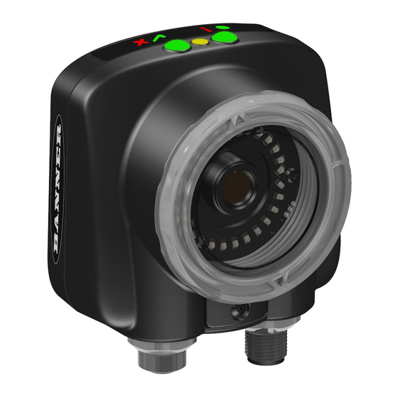
1 Overview of the Sensor The iVu Plus TG Gen2 Series Sensor sensor is used to monitor parts for type, size, orientation, shape, and location. No PC is required to configure the sensor. Instead, the sensor has a color touch screen display (either integrated with the sensor or available as a remote display) that you can use to set up and monitor inspections. -
Page 6: Installation
Remove this cover when setting up the sensor. When the display is not in use be sure to keep the display covered to protect it. If an integrated ring light is not used, another light source is needed. Various lights are available from Banner. Operating ®... -
Page 7: Installing And Connecting The Sensor
2.2 Installing and Connecting the Sensor The iVu Plus TG sensor requires a bracket for mounting. Three brackets are available from Banner. The brackets allow the sensor to be mounted either perpendicular to the part or at an adjustable angle. -
Page 8: Cable Connections For Integrated Display
Plus TG Gen2 Image Sensor 2.2.1 Cable Connections for Integrated Display The cable connections on the iVu Plus with integrated display are shown below, and power I/O connections (C) are defined in the Power I/O Connections table below. USB Connector... -
Page 9: Installing A Filter On Ivu Series Sensors
Plus TG Gen2 Image Sensor Power I/O Connections Pin # Wire Color Description Direction Green Output 2 Output Yellow Strobe Out (5V dc only) Output Gray Remote Teach Input Pink External Trigger Input Blue Common (Signal Ground) Input Ready... -
Page 10: Ivu Trigger, Remote Teach, And I/O Waveforms
Plus TG Gen2 Image Sensor 6. After the filter is installed, place the Focusing Window back into the housing while inserting the Locking Clip into the groove as shown. Groove 7. Press the Focusing Window onto the housing to make sure that it seats correctly (no gap between the window and housing). -
Page 11: Pnp (Low-To-High) Trigger And Remote Teach Input Waveforms
Plus TG Gen2 Image Sensor 2.3.1 PNP (Low-to-High) Trigger and Remote Teach Input Waveforms Power up Wire Color Function Pink Trigger Remote Gray Teach The sensor triggers from low to high, and Remote Teach behaves electrically like trigger. NOTE:... -
Page 12: Ivu Output Waveforms
Plus TG Gen2 Image Sensor NOTE: If the device used to trigger or remote teach the iVu Plus TG is a sinking device, these are the options regarding the use of a pull-up resistor: Option 1: Put a pull-up resistor, rated approximately 1k ohm, between the sensor's positive (+) voltage and the sensor's input as shown below. - Page 13 Plus TG Gen2 Image Sensor NOTE: Table 4: Expected iVu Output Signal Voltage +1 V www.bannerengineering.com - Tel: 763.544.3164...
-
Page 14: Major Features
Plus TG Gen2 Image Sensor 3 Major Features 3.1 Demo Mode The first time you power up the iVu Plus TG sensor, it starts in Demo Mode and allows you to choose whether to stay in Demo Mode or exit to Live Mode. Demo Mode uses stored images and inspection parameters that demonstrate how the sensor is set up without having to worry about focus, lighting, or triggers. -
Page 15: Blemish Sensor
Plus TG Gen2 Image Sensor 3.2.2 Blemish Sensor A Blemish type sensor can be used to find flaws on a part (for example, scratches on a disc), or it can be used to make sure a feature exists on a part. Although verifying a feature is present on a part is more commonly an Area sensor application, a Blemish sensor may be a better option when dealing with variable materials or uneven lighting. -
Page 16: Changing Running Inspections
2. Select the inspection to start and click the Start Running button that appears below it. 3.5 Imager Resolution The iVu Plus TG Gen2 Series Sensor includes an adjustable resolution up to 752×480 pixels. 3.6 iVu Plus Communication Summary of Ethernet and Serial The iVu Plus communicates with other devices via Ethernet or a UART serial communications port (RS-232). -
Page 17: Communication Channels
Plus TG Gen2 Image Sensor 3.6.1 Communication Channels The iVu Plus TG supports up to four communications channels. To access the channels, go to Main Menu > System > Communications. • Command Channel—a bi-directional communication protocol that currently supports ASCII and enables other devices to remotely control the iVu Plus sensor and access sensor results •... -
Page 18: Mask
Plus TG Gen2 Image Sensor 3.8 Mask Use this feature to place mask ROI(s) to exclude portions of an image from the running sensor. It is available on Area and Blemish sensors. Configuring a Mask on page 75 for more information. -
Page 19: Home Screen
Plus TG Gen2 Image Sensor 4 Home Screen The Home screen on the iVu Series sensor display is used to monitor inspections and to configure the sensor. Normally, the part being inspected is centered on the screen with the feature of interest bounded by the Region of Interest (ROI), a rectangle as shown below. -
Page 20: Image Without Annotations
Plus TG Gen2 Image Sensor 4.1.2 Image without Annotations Click the display mode icon to see the image without the annotations from the sensors. 4.1.3 Inspection Statistics To access the Inspection Statistics, click the Display mode icon The Inspection Statistic mode has three pages: •... - Page 21 Plus TG Gen2 Image Sensor Inspection Inputs The Inspection Input page has the sensor settings. Use this page to verify what inspection input settings were used on the latest inspection. Click + to expand the inspection information, or – to collapse the inspection information. Use the right arrows as a shortcut go to a sensor setting screen.
-
Page 22: Main Menu Reference
Plus TG Gen2 Image Sensor 5 Main Menu Reference 5.1 Main Menu The Main Menu has four sections: • Inspection—to modify inspection settings • Imager—to run the Auto Exposure routine and to make adjustments to functions like exposure, gain, and strobe •... -
Page 23: Icon Reference
Plus TG Gen2 Image Sensor 5.1.1 Icon Reference Action Icons Icon Description The Main Menu icon is displayed on the bottom-left corner of the sensor display on the Home screen. It provides access to sub-menus that are used to set up the sensor. -
Page 24: Display Icons
Plus TG Gen2 Image Sensor Icon Description The Add Mask icon displays on the left side of the screen when masking is enabled. Press to add a mask to the currently selected sensor. The Delete Mask icon displays on the left side of the screen when a mask is selected. Press to delete a mask from the currently selected sensor. -
Page 25: Sensors Menu
Plus TG Gen2 Image Sensor 5.2.1 Sensors Menu Main Menu > Inspection > Sensors This menu shows the list of sensor(s) that are included in the current inspection. Use the Add Sensor button add a new sensor into the current inspection. - Page 26 Plus TG Gen2 Image Sensor ROI and Mask Main Menu > Inspection > Sensors > Area > ROI and Mask The Region of Interest (ROI) is the user-defined area on the screen that the sensor will analyze. The ROI type can be rectangular, elliptical, or circular.
- Page 27 Plus TG Gen2 Image Sensor ROI and Mask Main Menu > Inspection > Sensors > Blemish > ROI and Mask The Region of Interest (ROI) is the user-defined area on the screen that the sensor will analyze. The ROI type can be rectangular, elliptical, or circular.
-
Page 28: Sort Menu
Plus TG Gen2 Image Sensor Percent Match Main Menu > Inspection > Sensors > Match > Percent Match The Percent Match setting adjusts for how closely the inspected part or label matches the reference part or label. The Percent Match scale is from 0 to 100 where 0 is the most tolerant and 100 is the least tolerant. Move the slider to the left or to the right. -
Page 29: Motion Menu
Plus TG Gen2 Image Sensor The Percent Match setting adjusts for how closely the inspected part or label matches the reference part or label. The Percent Match scale is from 0 to 100 where 0 is the most tolerant and 100 is the least tolerant. Move the slider to the left or to the right. -
Page 30: Properties Menu
Plus TG Gen2 Image Sensor Sensitivity Main Menu > Inspection > Motion > Sensitivity Sensitivity is used to fine-tune how sensitive the sensor is to finding a reference edge. The Sensitivity value helps account for light variations that might affect how well the sensor detects edges on inspected parts. The Sensitivity scale is from 0 to 100 where 0 means least sensitive and 100 means most sensitive. - Page 31 Plus TG Gen2 Image Sensor From the Stored Inspections menu click Select, Add New, Startup, Delete, or Set Name/ID Select Main Menu > Inspection > Stored Inspections > Select This screen is used to select a new running inspection. Select the name of the inspection to start, and click the Start Running button that displays.
-
Page 32: Imager Menu
Plus TG Gen2 Image Sensor The Startup button allows you to select the inspection to use as the startup inspection. The selected inspection will automatically start after power up. Delete Inspections Main Menu > Inspection > Stored Inspections > Delete The Delete button is used to delete stored inspections. -
Page 33: Gain
Plus TG Gen2 Image Sensor NOTE: This feature is not effective on the emulator. 5.3.3 Gain Main Menu > Imager > Gain Gain is an electronic boost to the image signal. Increasing Gain by using the '-' and '+' keys or moving the slider to the right increases image brightness without increasing exposure time. -
Page 34: Focus
Plus TG Gen2 Image Sensor 5.3.5 Focus Main Menu > Imager > Focus The Focus Number displayed at the bottom of this screen is used to fine-tune image focus. Loosen the lock on the lens cover, turn the focus ring on the sensor until the Focus Number peaks (or the image appears sharp), then lock the focus ring. -
Page 35: Fov (Field Of View)
Plus TG Gen2 Image Sensor External Main Menu > Imager > Strobe > External The External Strobe is a 5V output that can be used for an external light. Setting options are Always ON, Always OFF, or Exposure Based. If Exposure Based is selected, then the external light is on during the time the sensor is capturing an image. -
Page 36: Resolution
Plus TG Gen2 Image Sensor If the FOV has been modified and you want to quickly return to the default, click Set Default to restore the FOV to the default. The green box representing the FOV moves and the button changes to Set Max. The default for Fine resolution is 640×480 pixels and the default for Coarse resolution is 320×240 pixels. -
Page 37: System Menu
Plus TG Gen2 Image Sensor Coarse resolution has a maximum FOV of 376×240 pixels, and Fine resolution has a maximum FOV of 752×480 pixels. Fine resolution has 4 times more pixels than Coarse resolution. Inspection performance may be affected when using Fine resolution, depending on the application. -
Page 38: System Configuration
Plus TG Gen2 Image Sensor 5.4.2 System Configuration Main Menu > System > Configuration The Configuration menu options are: • Save sensor Configuration to the USB flash drive • Load sensor Configuration from the USB flash drive • Reset the sensor Configuration to defaults Save to USB Main Menu >... -
Page 39: System Information
Plus TG Gen2 Image Sensor 5.4.3 System Information Main Menu > System > Information The Information screen displays the following sensor information: • Serial Number • Firmware Version • Boot Number • Up Timer—the time elapsed since last boot of the sensor •... - Page 40 Plus TG Gen2 Image Sensor The sensor's Ethernet communications can be used to send data out the Ethernet port as part of an inspection, and remote devices can communicate with the sensor. The Ethernet I/O screen is where IP Address, Subnet Mask, and Gateway settings are configured.
- Page 41 Plus TG Gen2 Image Sensor The Port Status screen can be used to ensure data is entering and exiting the sensor. This can be useful for debugging issues such as improper wiring, mismatched baud rates, or other serial I/O issues.
- Page 42 Plus TG Gen2 Image Sensor WORD # WORD NAME Data Type 53-54 Frame Number 32-bit integer Sensor Type ID (Sensor 1) 16-bit integer 56-74 Sensor 1 Specific Data 16-bit integer Sensor Type ID (Sensor 2) 16-bit integer 76-94 Sensor 2 Specific Data...
- Page 43 Plus TG Gen2 Image Sensor Sensor Specific Data Sensor Location Sort Pattern Count 16-bit integer Sort Pattern 1 Count 16-bit integer Sort Pattern 2 Count 16-bit integer Sort Pattern 3 Count 16-bit integer Sort Pattern 4 Count 16-bit integer...
- Page 44 Plus TG Gen2 Image Sensor Custom Map Export Main Menu > System > Communications > Industrial Ethernet > Map > Custom > (Save icon) To export the Custom Map, Click to save a text listing of the map (Filename: iVuIEMap.csv) to an attached USB drive.
- Page 45 Plus TG Gen2 Image Sensor In the Delimiters screen, there are three delimiter options that you can set: • Field Delimiter, which determines what is used to separate data that the sensor is sending out to a remote device.
- Page 46 Plus TG Gen2 Image Sensor Output Format Main Menu > System > Communications > Data Export > Output Format In the Output Format screen, use the drop-down lists to select Start and End Strings as well a Delimiter. In the field at the bottom of the screen is an example of how the data will look when it is output.
- Page 47 Plus TG Gen2 Image Sensor NOTE: This setting affects both the Data Export Channel and Image Export Channel. Image Export Main Menu > System > Communications > Image Export When the Image Export Channel is enabled, the sensor will transmit the acquired image on every trigger. The image is transmitted as a bitmap (BMP) file.
-
Page 48: Discrete I/O
Plus TG Gen2 Image Sensor NOTE: This setting affects both the Data Export Channel and Image Export Channel. 5.4.6 Discrete I/O Main Menu > System > Discrete I/O The Discrete I/O options are used to adjust iVu input and output settings. - Page 49 Plus TG Gen2 Image Sensor Output 1, 2, and 3 Main Menu > System > Discrete I/O > Output (#) Output 1, 2, and 3 are setup separately to improve flexibility and simplicity. Output can be configured for Inspection Pass, Inspection Fail, Sensor Pass, Sensor Fail, Sort Pattern #1, Missed Trigger or System Error.
-
Page 50: Display Settings
Plus TG Gen2 Image Sensor Click on the yellow arrow button to access the Select Sensor screen. On the Select Sensor screen, the left column check box allows adding sensor position to be part of the logic that activates the output. -
Page 51: Reboot Sensor
The Firmware Update screen is used to load the latest sensor firmware. The Firmware Update screen lists the firmware versions it finds in the BANNER\FIRMWARE folder on the USB flash drive. When you receive a firmware update from Banner Engineering, be sure to put it in the BANNER\FIRMWARE folder on the USB flash drive. -
Page 52: Logs Menu
Plus TG Gen2 Image Sensor 5.5 Logs Menu Main Menu > Logs The Logs menu icon is on the Main Menu, and is used to set up, view, and save Inspection, Communication, and System Logs. 5.5.1 Inspection Logs Main Menu > Logs > Inspection Logs This menu provides for configuring and viewing Inspection Logs. -
Page 53: System Logs
Plus TG Gen2 Image Sensor The View Inspection Log screen is used to debug an inspection, and shows one inspection in read-only mode. Click the upper-left icon to cycle through views. When in Statistics view, the table title has arrows to switch between Inputs and Results of the Inspection. -
Page 54: Communication Logs
Plus TG Gen2 Image Sensor • Click the icon at the lower-right of the screen to save the System Log to the USB flash drive NOTE: System log will not log changes while in Demo mode. Additionally, the Emulator does not log changes. - Page 55 Plus TG Gen2 Image Sensor Image Export Log Main Menu > Logs > Communication Logs > Image Export The Image Export log is purely an output log so there is no receive (input) activity. Image Export is only available over Ethernet.
-
Page 56: Setting Up An Inspection
Plus TG Gen2 Image Sensor 6 Setting up an Inspection The device holds up to 30 inspections. Inspections may hold multiple sensors. To set up for an inspection: 1. Acquire a good image. 2. Configure the sensor(s) in the inspection 3. -
Page 57: Adjust The Focus On A Micro Video Lens Model
Plus TG Gen2 Image Sensor 6.1.1 Adjust the Focus on a Micro Video Lens Model 1. Use the supplied 1/16 in. hex key to loosen the Focusing Window locking screw (D), then adjust focus on the iVu Series sensor using the clear Focusing Window (B). -
Page 58: Using Ivu Gen1 And Gen2 Devices In The Same Application
Plus TG Gen2 Image Sensor C-Mount Models C-Mount Lens Lens Enclosure Retainer Ring (optional) Filter (optional) Filter Retainer Ring Tool NOTE: Filter Kits are available separately. 6.2 Using iVu Gen1 and Gen2 Devices in the Same Application Generation 1 and Generation 2 iVu devices can be used in the same application, however steps must be taken to ensure compatibility. -
Page 59: Configuring Sensors
From the Home screen, click inside the Region of Interest (ROI). The ROI is the visual area indicated by a dotted line on the inspection. In the Demo mode this will be the Banner logo. The dotted line will turn bold and have rotation and size icons in the corners. - Page 60 Plus TG Gen2 Image Sensor Area Sensor Blemish Sensor Match Sensor Sort Application The Edge Length Range slider adjusts the edge pixels in the The Area Range is used to set ROI. The slider of the Edge the size limits of a feature of Length Range screen shows all interest.
-
Page 61: Configuring An Area Sensor
Plus TG Gen2 Image Sensor 7.2 Configuring an Area Sensor NOTE: By default, the Trigger is set to Internal, and will continuously trigger based on a time interval setting. This may make it more difficult to make adjustments while setting up the sensor. The best practice is as follows: •... - Page 62 2. Resize and move the ROI to surround the feature of interest. In the Demo example, the feature of interest is the Banner logo as shown here. It is still red because the parameters need to be set. NOTE: When running an Area inspection, the sensor finds objects only within the ROI.
- Page 63 Plus TG Gen2 Image Sensor • Set the Pass Count parameter. The Minimum Pass Count is the minimum number of parts, labels, or features expected to fall within the specified criteria; the Maximum Pass Count is the maximum number expected to fall within the specified criteria.
-
Page 64: Configuring A Blemish Sensor
1. Adjust the Region of Interest (ROI). Resize the ROI so that it surrounds just the feature of interest. In the Blemish Demo example, the feature of interest includes the two irregular shapes below the Banner logo. 2. Adjust the parameters of the sensor by clicking inside the ROI then click the sensor name button. - Page 65 Plus TG Gen2 Image Sensor • Adjust the Sensitivity parameter. Sensitivity is used to fine-tune how sensitive the sensor is to finding blemish or other edges within the ROI. The Sensitivity value helps account for light variations that might affect how well the sensor detects edges.
- Page 66 Plus TG Gen2 Image Sensor 1. Use the brackets to set a tolerance for the pass/fail. Now the inspection for the blemish sensor is set up to be sensitive enough to find blemishes under the logo and fail the inspection.
-
Page 67: Configuring A Match Sensor
Plus TG Gen2 Image Sensor 7.4 Configuring a Match Sensor NOTE: By default, the Trigger is set to Internal, and will continuously trigger based on a time interval setting. This may make it more difficult to make adjustments while setting up the sensor. The best practice is as follows: •... - Page 68 Plus TG Gen2 Image Sensor 4. Click the Teach icon to teach the sensor this good reference part. 5. Set sensor parameters. • Adjust the Percent Match parameter. The Percent Match setting adjusts for how closely the inspected part or label matches the reference part or label.
- Page 69 Plus TG Gen2 Image Sensor NOTE: When running a Match inspection with annotations enabled, the sensor will highlight in green any pattern matches that meet or exceed the value specified for Percent Match. Patterns that are below the specified value for Percent Match (down to approximately 20%), or out of the Rotation Range (see below), will be colored yellow.
-
Page 70: Remote Teach
Plus TG Gen2 Image Sensor • Set the Pass Count parameter. The Minimum Pass Count is the minimum number of parts, labels, or features expected to fall within the specified criteria; the Maximum Pass Count is the maximum number expected to fall within the specified criteria. -
Page 71: Configuring A Sort Application
Plus TG Gen2 Image Sensor 7.5 Configuring a Sort Application NOTE: By default, the Trigger is set to Internal, and will continuously trigger based on a time interval setting. This may make it more difficult to make adjustments while setting up the sensor. The best practice is as follows: •... -
Page 72: Configuring Motion
Plus TG Gen2 Image Sensor Tip: Use the short-cut menu in the upper-right of the screen to select an ROI-type. Tip: For better results, make sure that the ROI bounds the image of the pattern as tightly as possible. -
Page 73: Number Of Edges
Plus TG Gen2 Image Sensor 7.6.1 Number of Edges Main Menu > Inspection > Motion > Number of Edges On the Number of Edges screen, use the radio buttons to select One Edge or Two Edges. If One Edge is selected, motion is tracked in one direction (by default, horizontally);... - Page 74 Plus TG Gen2 Image Sensor 2. Click Add to add the selected sensor. 3. Click in the Sensor Setup area (Black button) to display the input parameter menu for that sensor. 4. Click on the yellow down-arrow button to access sensor management functions.
-
Page 75: Configuring A Mask
Plus TG Gen2 Image Sensor 7.8 Configuring a Mask A mask created for a sensor will not apply to any other sensors in the inspection. The mask ROI type can be rectangular, elliptical, or circular. Use up to ten masks per sensor. -
Page 76: Communications Guide
Plus TG Gen2 Image Sensor 8 Communications Guide 8.1 iVu Plus Communication Summary of Ethernet and Serial The iVu Plus communicates with other devices via Ethernet or a UART serial communications port (RS-232). In order to establish an Ethernet connection to the sensor, the external device must be configured with the correct IP address and TCP port to communicate. -
Page 77: Data Export
Plus TG Gen2 Image Sensor do trigger\x0D\x0A OK\x0D\x0A Control Device, which can be a PLC, PC program, or a terminal Response Frame Request Frame iVu Plus TG Sensor The following are some of the functionality available via the command channel: •... -
Page 78: Image Export
Plus TG Gen2 Image Sensor • Sensor Result ◦ Name ◦ Pass/Fail ◦ Sensor Result (see Table 11 on page 78 for additional information) • Inspection Time (ms) Table 11: Sensor Results Sensor Type Data to Export Area Count... -
Page 79: Enabling Communications
Plus TG Gen2 Image Sensor Byte Offset Field Size in Data Type Description Bytes 20-23 Image Size UInt32 Number of bytes (Windows BMP image) 24-27 Image Frame Number UInt32 Most recently snapped image frame number 28-29 Image Width UInt16... - Page 80 Plus TG Gen2 Image Sensor 4. In the Internet Protocol (TCP/IP) Properties dialog, select Use the following IP address and make sure that the IP address is 192.168.0.2, and the subnet mask is 255.255.255.0. Windows 7 1. Open Network Connections by clicking on the Start button, then selecting the Control Panel followed by Network and Internet, and clicking Manage network connections.
- Page 81 Plus TG Gen2 Image Sensor 4. In the Internet Protocol (TCP/IPv4) Properties dialog, select Use the following IP address and make sure that the IP address is 192.168.0.2, and the subnet mask is 255.255.255.0. Sensor Setup for Ethernet Communications 1.
- Page 82 Plus TG Gen2 Image Sensor Valid end-of-frame delimiters are: <comma>, <colon>, <semicolon>, <CR>, <CR><LF>, <LF><CR>, or <ETX>. c. Verify that the iVu receives and transmits data correctly. 3. To enable Data Export over Ethernet: a. Go to Main Menu > System > Communications > Data Export > Connection and select Serial I/O from the drop-down.
-
Page 83: Setting Up Serial Communications
Plus TG Gen2 Image Sensor d. Go to Main Menu > System > Communications > Data Export > Advanced. During the Data and Image export operation the sensor's output channels might become full. This can occur if the sensor is producing export data (frames) faster than the data can be exported from the device (due to bandwidth limitations) or faster than the client is reading the channel export data. - Page 84 Plus TG Gen2 Image Sensor 3. To enable the command channel over the serial connection: a. Go to Main Menu > System > Communications > Command Channel > Connection and select Serial I/O. b. Configure the field and end-of-frame delimiters. Go to Main Menu > System > Communications >...
- Page 85 Plus TG Gen2 Image Sensor b. Go to Main Menu > System > Communications > Data Export > Data To Export and select the inspection data to export. c. Go to Main Menu > System > Communications > Data Export > Output Format and select the Start String, Delimiter, and End String.
-
Page 86: Testing And Troubleshooting Ivu Plus Communications
Plus TG Gen2 Image Sensor During the Data and Image export operation the sensor's output channels might become full. This can occur if the sensor is producing export data (frames) faster than the data can be exported from the device (due to bandwidth limitations) or faster than the client is reading the channel export data. -
Page 87: Ethernet I/O
Plus TG Gen2 Image Sensor • When a client closes the connection, a log entry indicates that the channel is no longer being listened to 8.3.2 Ethernet I/O Ethernet I/O Status The Ethernet I/O Status screen can be used to verify that the Ethernet wiring has been correctly set up. In addition to determining if the link has been established, incoming and outgoing traffic can be monitored. - Page 88 Plus TG Gen2 Image Sensor Verifying Basic Receive Functionality To verify the iVu can receive request frames from the requesting device: 1. On the iVu Sensor, go to the Main Menu > System > Communications > Serial I/O > Port Status screen.
-
Page 89: Command Channel Primer
Plus TG Gen2 Image Sensor 8.4 Command Channel Primer 8.4.1 Command Channel Commands All iVu command channel request command frames use the following syntax: >> command group item value<EOF> Notes <EOF> is the end-of-frame delimiter. See below for a description. -
Page 90: Conventions Used For Examples
Plus TG Gen2 Image Sensor Command Channel Response Frames The iVu responds to all request frames with one or two responses depending on the type of command. Do commands All do commands are followed by one response that identifies the command status. For example: >>... -
Page 91: Command Channel Reference
Plus TG Gen2 Image Sensor 5. Get the pattern names that are stored in the iVu sensor. >> get sort_result patternnames\x0D\x0A << OK\x0D\x0A << "pattern_1","pattern_2"x0D\x0A How to Execute a Product Change Using the Command Channel 1. Make sure that the Command Channel is enabled using either Ethernet or Serial I/O ( Main Menu > System >... -
Page 92: System Command Group
Plus TG Gen2 Image Sensor System Command Group Command Group Item Description System Reboot Reboots the sensor. Pre-empts other commands except Save. System Save Saves inspection and configuration parameters. Blocks until finished. Should be used sparingly. Ethernet IPAddress Get the current active IP address of the sensor as a string. - Page 93 Plus TG Gen2 Image Sensor Examples >> set trigger mode command\x0D\x0A << OK\x0D\x0A >> get trigger mode\x0D\x0A << OK\x0D\x0A << Command\x0D\x0A >> do trigger\x0D\x0A << OK\x0D\x0A Imager Command Group Command Group Item Description Imager Gain The sensor's value used to electronically brighten all image pixels This value can be modified using the sensor's touchscreen.
-
Page 94: Productchange Command Group
Plus TG Gen2 Image Sensor ProductChange Command Group Command Group Item Description ProductChange [Name] Forces the sensor to switch to the specified inspection. The sensor does not transmit a response until the sensor has completed the action. Inspections results will be invalid until the next trigger. -
Page 95: Area_Result Command Group
Plus TG Gen2 Image Sensor Examples >> get inspection status\x0D\x0A << OK\x0D\x0A << Fail\x0D\x0A >> get inspection executiontime\x0D\x0A << OK\x0D\x0A << 37.739\x0D\x0A AREA_RESULT Command Group Command Group Item Description AREA_RESULT Count The number of detected areas. AREA_RESULT MinArea The size of the smallest detected area. -
Page 96: Blemish_History Command Group
Plus TG Gen2 Image Sensor Examples >> get blemish_result count\x0D\x0A << OK\x0D\x0A << 4\x0D\x0A >> get blemish_result minedgelength\x0D\x0A << OK\x0D\x0A << 22\x0D\x0A BLEMISH_HISTORY Command Group Command Group Item Description BLEMISH_HISTORY MinCount The minimum number of detected blemishes, since history was last cleared. -
Page 97: Multiple Sensors Inspection
Plus TG Gen2 Image Sensor Command Group Item Description MATCH_HISTORY MaxPercent The maximum detected match percentage, since history was last cleared. Examples >> get match_history count\x0D\x0A << OK\x0D\x0A << 1\x0D\x0A >> get match_history maxcount\x0D\x0A << OK\x0D\x0A << 6\x0D\x0A SORT_RESULT Command Group... -
Page 98: Command Channel Command Status Register
Plus TG Gen2 Image Sensor Notice that <Area1> is the sensor name of an Area Sensor Type in the current inspection. >> get blemish_history <Blemish1> minedgelength\x0D\x0A << OK\x0D\x0A << 22\x0D\x0A Notice that <Blemish1> is the sensor name of a Blemish Sensor Type in the current inspection. -
Page 99: Ivu Discovery Protocol
Attempt to use a command without a sensor name in a multi- sensor inspection 8.5 iVu Discovery Protocol The iVu Discovery Protocol is a method by which Banner's iVu Vision sensors can be dynamically discovered on an Ethernet network. 8.5.1 Overview The iVu Discovery Protocol is a method to dynamically discover Banner's iVu Vision sensors on an Ethernet network. - Page 100 100 milliseconds or more. This and the following packet capture examples were done using a freely-available network tracing and troubleshooting software called Wireshark. Banner Engineering Corporation does not provide support for this product nor endorses it. www.bannerengineering.com - Tel: 763.544.3164...
- Page 101 Plus TG Gen2 Image Sensor NOTE: – In some situations, it is possible for a PC to receive a copy of the packet it sent. This condition is subject to the operating system and/or network configuration. If received, such a received packet should be detected (by checking the message type) and discarded.
- Page 102 Plus TG Gen2 Image Sensor DISCOVER_SETIP Message The DISCOVER_SETIP message is sent by the controlling PC to instruct a sensor to change its IP address, subnet mask and default gateway. The message sent by the PC must always have the following parameters in the body portion: Either MAC or SerialNumber or both.
-
Page 103: Message Flow
Plus TG Gen2 Image Sensor 8.5.4 Message Flow Below are some examples of typical message flows for various interactions with the sensor. Discovery of a Sensor 1. PC broadcasts a DISCOVER message Only the header values need to be filled •... - Page 104 Plus TG Gen2 Image Sensor • SerialNumber (“SerialNumber=P01238710163241048”) • Version (“Version=TB_v1.1.4”) • Name (“Name=Sensor1”) • MAC (“MAC=00:11:22:33:44:55”) • IP (“IP=192.168.0.1”) • NetMask (“NetMask=255.255.255.0”) • Gateway (“Gateway=0.0.0.0”) The body of the message will look like this: SerialNumber=P01238710163241048,Version=TB_v1.1.4,Name=Sensor1,MAC=00:11:22:33:44: 55,IP=192.168.0.1,NetMask=255.255.255.0,Gateway=0.0.0.0 • The packet is broadcast on the network to port 19995. The sensor uses a pseudo-random back-off time to minimize collisions with other sensors.
- Page 105 Plus TG Gen2 Image Sensor - The check for duplicate IP address will not be performed > If the values do not pass the syntax check, the packet is discarded - The attempt is logged in the System Log - A DISCOVER_REPLY (RPLY) reply with current values is generated and sent.
- Page 106 Plus TG Gen2 Image Sensor For example, Gateway address of 255.255.255.255 is not allowed IP address of 0.0.0.0 or 255.255.255.255 is not allowed The check for duplicate IP address will not be performed • If the values do not pass the syntax check, the packet is...
-
Page 107: Industrial Ethernet Overview
Plus TG Gen2 Image Sensor 9 Industrial Ethernet Overview 9.1 Device Setup 9.1.1 Set IP Address When shipped, the device is assigned a default IP address - 192.168.0.1, a default Subnet Mask - 255.255.255.0, and a default gateway - 0.0.0.0. To change these defaults, click on Main Menu > System > Communications > Ethernet I/O. -
Page 108: Ivu Output Values
Plus TG Gen2 Image Sensor 9.2.2 iVu Output Values Using output values, the following information can be obtained: • ACK bits (acknowledgement bits) for input commands, including error codes • System indicators (Ready, Pass/Fail, Read/No Read, Output signals, Command Error, etc.) •... -
Page 109: General Command Execution
Plus TG Gen2 Image Sensor 9.3.1 General Command Execution Point of View of PLC Following rules apply for the usage of input bit commands: • Only one iVu input bit can be set at a time. • Corresponding ACK bits are only set high on... -
Page 110: Inputs To Ivu (Outputs From Plc)
Plus TG Gen2 Image Sensor 9.4.1 Inputs to iVu (Outputs from PLC) PLC Assembly Instance 112 (0x70) - 6 Registers (iVu Inputs/PLC Outputs) Data transfer direction: Originator (PLC) to Target (iVu Plus). Assembly Instance 112 (0x70) is a small group of registers used for basic control of the iVu Plus. -
Page 111: Multiple Sensors Mapping Options
Plus TG Gen2 Image Sensor WORD # WORD NAME DATA TYPE Sensor P/F Coil 16-bit integer 17-29 reserved 16-bit integer PLC Assembly Instance 101 (0x65) - 240 Registers (iVu Outputs/PLC Inputs) Assembly Instance 101 provides space for sensor-specific information. - Page 112 Plus TG Gen2 Image Sensor WORD # WORD NAME Data Type 179-228 Command Response Data 100 Byte Array 229-239 reserved 16-bit integer NOTE: If the inspection contains more than five sensors, the sensor after the fifth one will not be on the map.
- Page 113 Plus TG Gen2 Image Sensor The custom map allows for customization of sensor data on the map. The user selects data items of interest for each sensor type. This is recommended when the execution order of sensor types varies across inspections or when using more than five sensors.
- Page 114 Plus TG Gen2 Image Sensor The bottom of the screen shows the word use on the customizable space. In the screenshot above, seven words have been used for one Area sensor "Area (1)". Use the yellow arrow button next to the Area sensor row to go to the Area Sensor Data in the following graphic.
-
Page 115: Input And Output Flags Bits
Plus TG Gen2 Image Sensor User may continue to add more data from any sensor type as required or reserve more sensors into the customizable space. Sensor Name and Sensor Type ID are global settings that are part of any individual sensor reservation. When they are checked, they will be inserted into each sensor reservation. -
Page 116: Configuration Assembly Object
Plus TG Gen2 Image Sensor 9.4.5 Configuration Assembly Object The iVuPlus EIP implementation does not support an assembly object configuration instance. However, one is required for creation of implicit Class 1 connections on a ControlLogix family PLC. Therefore, a configuration instance is defined as instance number 0x80 (128 decimal). - Page 117 Plus TG Gen2 Image Sensor 2. Click Next. 3. Select the Register and EDS file(s) option. www.bannerengineering.com - Tel: 763.544.3164...
- Page 118 Plus TG Gen2 Image Sensor 4. Browse to locate the EDS file and click Next. 5. Click Next to register the tested file. www.bannerengineering.com - Tel: 763.544.3164...
- Page 119 Plus TG Gen2 Image Sensor 6. Click Next when you see the icon associated with the EDS file. 7. Click Next to register the EDS file. www.bannerengineering.com - Tel: 763.544.3164...
- Page 120 Plus TG Gen2 Image Sensor 8. Click Finish to close the EDS Wizard window. 9. Right-click on the PLC's Ethernet adapter and select New Module... www.bannerengineering.com - Tel: 763.544.3164...
- Page 121 Plus TG Gen2 Image Sensor 10. Locate iVu Plus from the displayed list and click Create. 11. Enter a name, optional description, and IP address for the iVu Plus. www.bannerengineering.com - Tel: 763.544.3164...
- Page 122 Plus TG Gen2 Image Sensor 12. Click Change in the Module Definition field. 13. Select the desired connection in the Module Definition window. Each of the items in the Name drop-down menu represents a fixed grouping of input and output assembly instances (see below).
-
Page 123: Rslogix5000 Configuration
To create an implicit Class 1 configuration to the iVu Plus using EIP when using a ControlLogix family PLC, configure the iVu Plus as a “Generic Ethernet Module” under the ENET_MODULE. The following is a sample setup of Banner sensor: 1. - Page 124 Plus TG Gen2 Image Sensor 3. Configure Module Properties. NOTE: The data type in the Comm Format must be changed to an INT. Inputs to iVu (Outputs from PLC) on page 110 and Outputs from the iVu (Inputs to the PLC) on page 110 for more information on each specific assembly instance.
- Page 125 Plus TG Gen2 Image Sensor Figure 3. PLC Input Assembly (100), PLC Output Assembly (112) Figure 4. PLC Input Assembly (101), PLC Output Assembly (113) www.bannerengineering.com - Tel: 763.544.3164...
- Page 126 Plus TG Gen2 Image Sensor Figure 5. Select or deselect Unicast Connection as desired NOTE: The minimum allowed RPI is 50 ms. 4. If the module configuration was successful, the following information should be displayed: If the module configuration was not successful, the RSLogix 5000 software will indicate errors similar to the ones displayed below: •...
- Page 127 Plus TG Gen2 Image Sensor 5. Locate the memory map setup from Banner module to PLC memory map. C = Configuration (not used) I = Inputs to PLC (outputs from iVu Plus) O = Outputs from PLC (inputs to iVu Plus)
- Page 128 Plus TG Gen2 Image Sensor The iVu Plus memory map expanded. I = Inputs to PLC (outputs from iVu Plus). Sample map demonstrating string values: Figure 6. Memory Map: Default NOTE: ControlLogix string format. "iVu Plus Image Sensor" www.bannerengineering.com - Tel: 763.544.3164...
-
Page 129: Modbus/Tcp
Plus TG Gen2 Image Sensor All data is initially transferred as "INT" data type. An ASCII string looks like gibberish in this format. Changing the "style" to ASCII instead of "Decimal" reveals the correct string data. Figure 7. Memory Map: "Style" changed to ASCII 9.5 Modbus/TCP... - Page 130 Plus TG Gen2 Image Sensor 05: Force Single Coil Register Bit Position WORD Name 00010 reserved 00011 reserved 00012 reserved 00013 reserved 00014 reserved 00015 reserved 00016 Command Table 21: Input ACK Bits (Inputs 10001-10016) 02: Read Input Status...
-
Page 131: Ivu Plus Input Values
Plus TG Gen2 Image Sensor 02: Read Input Status Register Bit Position WORD Name 10027 reserved 10028 reserved 10029 Missed Trigger 10030 Teach Error 10031 System Error 10032 Execution Error 9.5.1 iVu Plus Input Values Holding Registers (40000) are used by the PLC or HMI to write values to the iVu Plus sensor. To write, use function codes 6 (Preset Single Register) or 16 (Preset Multiple Registers). - Page 132 Plus TG Gen2 Image Sensor Table 24: iVu Plus Output Values (Modbus/TCP Input or Holding Registers): DEFAULT MAP 04: Read Input Registers or 03: Read Holding Registers Input REG # Holding REG # WORD NAME DATA TYPE 1001 Input ACK Bits (see Flags on...
- Page 133 Plus TG Gen2 Image Sensor Sensor Specific Data Data Size Area Range Minimum 32- bit Integer Area Range Maximum 32- bit Integer Table 26: Blemish Sensor Type ID = 3 Sensor Specific Data Sensor Location Blemish Count 32- bit Integer...
- Page 134 Plus TG Gen2 Image Sensor Table 29: iVu Plus Output Values (Modbus/TCP Input or Holding Registers): CUSTOM MAP 04: Read Input Registers or 03: Read Holding Registers Input REG # Holding REG # WORD NAME DATA TYPE 1001 Input ACK Bits (see...
- Page 135 Plus TG Gen2 Image Sensor The bottom of the screen shows the word use on the customizable space. In the screenshot above, seven words have been used for one Area sensor "Area (1)". Use the yellow arrow button next to the Area sensor row to go to the Area Sensor Data in the following graphic.
-
Page 136: Flags
Plus TG Gen2 Image Sensor User may continue to add more data from any sensor type as required or reserve more sensors into the customizable space. Sensor Name and Sensor Type ID are global settings that are part of any individual sensor reservation. When they are checked, they will be inserted into each sensor reservation. -
Page 137: Plc5 And Slc 5 (Pccc)
Plus TG Gen2 Image Sensor 9.6 PLC5 and SLC 5 (PCCC) Allen-Bradley’s PLC5 and SLC 500 family of devices use PCCC communications protocol. iVu Plus supports these PLCs using input and output register arrays. The Output Flags, ACK Flags and Input Flags bit definitions are the same as defined in the EIP Assembly Objects section. - Page 138 Plus TG Gen2 Image Sensor 2. Read. IP Address of the iVu Plus is entered here. 3. Write. In the below example, message command writing to N14 table on the iVu Plus from the N14 table of the PLC.
-
Page 139: Inputs To Ivu (Outputs From Plc)
Plus TG Gen2 Image Sensor 4. Write. IP address of the iVu Plus is entered here. 9.6.2 Inputs to iVu (Outputs from PLC) The registers below are used by the PLC to push values to the iVu Plus sensor. MSG (message) commands are used to write (N14) to the sensor. - Page 140 Plus TG Gen2 Image Sensor Default Map Main Menu > System > Communications > Industrial EtherNet > Map > Default Automatically maps sensor data for each inspection. Recommended when execution order of sensor types is the same across inspections. When inspection has multiple sensors, the first 5 sensor results will be shown starting at offset 55.
- Page 141 Plus TG Gen2 Image Sensor Table 36: Blemish Sensor Type ID = 3 Sensor Specific Data Sensor Location Blemish Count 32- bit integer Blemish Min Edge Length 32- bit integer Blemish Min Edge Length 32- bit integer Table 37: Match Sensor Type ID = 4...
- Page 142 Plus TG Gen2 Image Sensor WORD # WORD NAME Data Type 12-13 Missed Triggers 32-bit integer 14-15 Current Inspection Time Float Sensor Pass/Fail Coil 16-bit integer 17-29 reserved 16-bit integer 30-52 Inspection Name 2-Word Length + 20-unicode chars 53-54...
- Page 143 Plus TG Gen2 Image Sensor The bottom of the screen shows the word use on the customizable space. In the screenshot above, seven words have been used for one Area sensor "Area (1)". Use the yellow arrow button next to the Area sensor row to go to the Area Sensor Data in the following graphic.
-
Page 144: Input And Output Flags
(masters) and peripheral devices (slaves) exchange data in real time. The image sensor, iVu Plus TG Gen2 , supports PROFINET IO. The data communication protocol is TCP/IP; the data transmission medium is copper wire; the PROFINET conformance class is CC-A. -
Page 145: Ivu Profinet Io Data Model
Plus TG Gen2 Image Sensor • Diagnostics. NOTE: A single iVu Plus GSD file describes both the iVu Plus TG and the iVu Plus BCR. 9.7.2 iVu PROFINET IO Data Model The PROFINET IO data model is based on the typical, expandable field device that has a backplane with slots. Modules and submodules have different functionalities. - Page 146 Plus TG Gen2 Image Sensor 3. Click on Communications. 4. Click on Industrial Ethernet. Click on Connection. NOTE: The default Industrial Ethernet Connection setting is set to Disabled. 5. Click on PROFINET in the drop-down menu. www.bannerengineering.com - Tel: 763.544.3164...
- Page 147 Plus TG Gen2 Image Sensor 6. Click (only one time) on the Arrow button on the bottom left to return to the Industrial Ethernet window. 7. Click on Map to configure the PROFINET module map. NOTE: The PROFINET module map displays S1 SS1 and S1 SS2 by default. S1 represents Slot 1, SS1 represents SubSlot 1;...
- Page 148 Plus TG Gen2 Image Sensor 8. Click on S2 to go to the configuration window and add a submodule . 9. Click on the Drop-Down Arrow next to Disabled to open the list of submodule slots. 10. Select a submodule and hit enter.
- Page 149 Plus TG Gen2 Image Sensor Table 43: Command Channel Module (Ident 0x00000030) Number of Physical Subslots Subslot Label Subslot Number 3.1 Command Channel Command submodules 1 (0x1) 3.2 Command Channel Response submodules 2 (0x2) Description of Submodules Table 44: Supported Submodules and Locations...
- Page 150 Plus TG Gen2 Image Sensor Device Control Submodule The Device Control Submodule contains controller (PLC) input and output data, including device controls for the iVu Plus. The user-enabled Device Control Submodule is optional and plugged into Slot 1 Subslot 2 by default. The user can remove...
- Page 151 Plus TG Gen2 Image Sensor Sensor-Specific Data Data Size Area Range Maximum 32‐bit Integer Table 49: Blemish Sensor Type ID = 3 Sensor-Specific Data Data Size Blemish Count 32‐bit Integer Blemish Minimum Edge Length 32‐bit Integer Blemish Maximum Edge Length 32‐bit Integer...
- Page 152 Plus TG Gen2 Image Sensor Submodule PLC Input Data PLC Output Data Name Ident No. Name Type Name Type Frame number Unsigned32 256-Byte Custom Map 0x00032 Not applicable Not applicable User-mapped Sensor Result Data Block 256-byte OctetString Frame number...
- Page 153 Plus TG Gen2 Image Sensor On the Area Sensor Data screen above, Area Count, Area Range Min and Area Range Max are available to add into the customizable space. The number to the right of each item shows how many words are required to display the data.
- Page 154 The Command Channel Command Submodules contain controller (PLC) output data and command channel request data. The user-enabled submodules are optional. On the iVu Plus TG Gen2 device the submodule is plugged into Slot 3 Subslot The Command Channel Command Submodule has four versions with 16, 32, 64, or 128 bytes, depending on the required length of the input string.
- Page 155 Plus TG Gen2 Image Sensor Table 55: 64-Character Text Command Submodule (Ident 0x00014) PLC Output Data Name Output Data Type PLC Input Data Name Input Data Type Flag indicates when to apply the command Unsigned16 Not applicable Not applicable...
- Page 156 Plus TG Gen2 Image Sensor Table 57: Numeric Response Submodule (Ident 0x00050) PLC Input Data Name Input Data Type PLC Output Data Name Output Data Type Numeric Command Status Unsigned16 Not applicable Not applicable 16-bit integer command response Unsigned16...
-
Page 157: Configuration Instructions
Installing the Banner iVu Plus GSD File Use these instructions to install the Banner iVu Plus GSD file in the Siemens TIA Portal (v13) software. Use these instructions as a basis for installing the Banner iVu Plus GSD file in another controller (PLC). - Page 158 Plus TG Gen2 Image Sensor 5. Click Devices & networks when the project has been uploaded. 6. Click Configure networks. Network view displays. www.bannerengineering.com - Tel: 763.544.3164...
- Page 159 Plus TG Gen2 Image Sensor 7. Click Options and select Install general station description file (GSD). The Install general station description file window opens. 8. Click the browse button (...) to the right of the Source path field. 9. Navigate to the location the iVu Plus GSD file was downloaded to.
- Page 160 The system installs the iVu Plus GSD file and places it in the Hardware catalog. In the above example, the iVu Plus GSD file is located under Other field devices > PROFINET IO > Sensors > Banner Engineering Corp. > Banner Vision Sensors >...
- Page 161 Plus TG Gen2 Image Sensor 4. Click Devices & networks when the project has been uploaded. www.bannerengineering.com - Tel: 763.544.3164...
- Page 162 Plus TG Gen2 Image Sensor 5. Click Configure networks. Network view displays. NOTE: For Step 6 through Step 10, Network view must be open. www.bannerengineering.com - Tel: 763.544.3164...
- Page 163 In the above example, the iVu Plus device is located under Other field devices > PROFINET IO > Sensors > Banner Engineering Corp. > Banner Vision Sensors > iVu Series. 7. Select the device and add it to the configuration.
- Page 164 Plus TG Gen2 Image Sensor 8. Click the green square on the iVu Plus TG icon. Drag the pointer to the green square on the PLC_1 icon to connect the device to the controller (PLC). The connection is made.
- Page 165 Plus TG Gen2 Image Sensor 10. Select Set IP address in the project. The project sets the IP address of the device. 11. Enter the IP address. 12. Right-click on the device icon and select Online & diagnostics. The Online & diagnostics window displays.
- Page 166 Plus TG Gen2 Image Sensor 14. Click Accessible devices. The Select device window searches the network for available devices. 15. Determine the device to be adjusted via the MAC address and select it. NOTE: Use the iVu Plus touch screen to find the MAC address. Main Menu > System >...
- Page 167 Plus TG Gen2 Image Sensor 1. Open a project and click on Devices & networks to go to the Network view. Network view displays. 2. Double-click on the iVu Plus TG icon to bring up Device view. 3. Click on the iVu Plus icon in the graphic area of Device view to bring up the Module properties window.
- Page 168 Plus TG Gen2 Image Sensor 9. Right-click on the device icon and select Online & diagnostics. The Online & diagnostics window displays. 10. Select Assign name under Functions. The Assign name window displays. The devices in the network are discovered. The Name column is blank.
- Page 169 Using Siemens SIMATIC STEP 7 (v5.5) Software Installing the Banner iVu Plus GSD File Use these instructions to install the Banner iVu Plus GSD file in the Siemens SIMATIC STEP 7 (v5.5) software. 1. Start Siemens SIMATIC Manager. 2. Select an existing project and open it.
- Page 170 The Hardware configuration window opens. 5. In the Hardware configuration window, click Options > Install GSD File..The Install GSD Files window displays. 6. Browse to the location of the saved Banner iVu Plus GSD file. www.bannerengineering.com - Tel: 763.544.3164...
- Page 171 9. Check the Catalog option. The Hardware catalog appears on the right side of the Hardware configuration window. The location in the Hardware catalog is PROFINET IO > Additional Field Devices > Sensors > Banner Vision Sensors > iVu Series ®...
- Page 172 Plus TG Gen2 Image Sensor 4. Double-click on the Hardware icon in the Station level window to open the Hardware configuration window. 5. Right-click on the PN-IO line in the CPU module of the Station window and select Insert PROFINET IO System.
- Page 173 Plus TG Gen2 Image Sensor 3. Select the Station (PLC) from the Object Hierarchy list. 4. Double-click on the Hardware icon in the Station level window to open the Hardware configuration window. 5. Select PLC > Ethernet > Edit Ethernet Node.
- Page 174 Plus TG Gen2 Image Sensor 6. Click Browse... under Nodes accessible online in the Edit Ethernet Node window. This starts a search for all PROFINET devices on the network and shows the found devices. 7. Select the device to be modified.
- Page 175 Plus TG Gen2 Image Sensor 8. Click OK. The Edit Ethernet Node window is updated. 9. Set the IP address to the desired value. 10. Click Assign IP Configuration at the bottom left of the Set IP configuration section.
- Page 176 Plus TG Gen2 Image Sensor 3. Select a Station (PLC) from the Object Hierarchy list. 4. Double-click on the Hardware icon in the Station level window to open the Hardware configuration window. 5. Select PLC > Ethernet > Edit Ethernet Node.
- Page 177 Plus TG Gen2 Image Sensor 6. Click Browse... under Nodes accessible online in the Edit Ethernet Node window. ® This starts a search for all PROFINET devices on the network and shows the found devices. 7. Select the device to be modified.
- Page 178 Plus TG Gen2 Image Sensor 8. Click OK. The Edit Ethernet Node window is updated. 9. Enter a name with lower case letters in the Device name field. 10. Click Assign Name. The Device name is updated. If a failed update message is returned, the new name did not meet the naming requirements.
-
Page 179: Sample Timing Diagram
Plus TG Gen2 Image Sensor 9.8 Sample Timing Diagram X, Y, Z: Represent snapshot in time Product Change X+Y+Z Product Change Ready Product Change ProductChange ProductChange ProductChange Verify : Verify : ACK = ‘1 ’ Ready = 1 Ready = 1... - Page 180 Plus TG Gen2 Image Sensor Teach Latch X + Y X + Y + Z Teach Latch Ready Teach Latch ACK TeachLatch TeachLatch TeachLatch ACK Verify : Verify : = ‘1 ’ Ready = 1 Ready = 1 Teach will...
- Page 181 Plus TG Gen2 Image Sensor Trigger X + Y X + Y + Z Trigger Ready TriggerACK Trigger = 1 Trigger = 0 Verify : Verify : TriggerACK = ‘1 ’ Ready = 1 Ready = 1 Read Results...
-
Page 182: Command Channel Command Status Register
Plus TG Gen2 Image Sensor Gated Trigger X + Y X + Y + Z M Gated Trigger Ready Gated Trigger ACK GatedTrigger GatedTrigger GatedTrigger GatedTrigger = 0 (Abort ) Inspection could not be completed GatedTriggerACK Verify : Verify : = ‘1 ’... -
Page 183: Networking And Tcp/Ip Diagnostics
Plus TG Gen2 Image Sensor 2. Examine the small orange Ethernet link light located on the top of camera body, between the Pass/Fail and System Status LEDs. The light should be either on or blinking. 3. Go to the System > Logs > System Log page, and verify that the log entry indicates that the Ethernet link is up: 4. - Page 184 Plus TG Gen2 Image Sensor 4. Press the Status button on the same page, and go to the Ethernet I/O Status page: 5. On the PC attached to your LAN, open the Command window. To do this, press Start > Run, and then type in cmd and press the OK button.
-
Page 185: Industrial Protocols Troubleshooting
Plus TG Gen2 Image Sensor 8. You should also see the Packets Received and Packets Sent count on the Ethernet I/O Status page in the camera increment by at least 4. 9. If the output of the ping command shows request timeouts, try the following: •... - Page 186 Plus TG Gen2 Image Sensor In addition, EtherNet/IP implements I/O messaging. I/O messaging allows two devices, iVu sensor and the PLC, to continuously synchronize data sets between each other. These data sets are called Input and Output Assemblies. iVu device consumes PLC output assemblies, and produces PLC input assemblies.
- Page 187 Plus TG Gen2 Image Sensor After the CIP and I/O connections are established, the Industrial Protocols Status page will show the details of the connection: Most of the errors in establishing the CIP and I/O connections have to do with specifying the proper Input and Output assembly IDs and sizes.
- Page 188 Plus TG Gen2 Image Sensor Accessing the Sensor's Communication Logs ® PROFINET communication activity is recorded in the iVu Plus sensor's communication logs. Use these instructions to access the sensor's communication logs via the sensor's touch screen. 1. Click on the Wrench button on the iVu Plus Home screen.
- Page 189 Plus TG Gen2 Image Sensor 2. Click on Logs. 3. Click on Communication Logs. 4. Click on Industrial Ethernet. www.bannerengineering.com - Tel: 763.544.3164...
- Page 190 Plus TG Gen2 Image Sensor 5. Click on View Logs. NOTE: Green communication log icons mean flawless communication. Red communication icons mean communication errors. www.bannerengineering.com - Tel: 763.544.3164...
- Page 191 Plus TG Gen2 Image Sensor 6. Click on the Arrow button on any log entry in the communication log to access the Communication Log Detail window. NOTE: An expanded description of the communication supports better diagnostics. www.bannerengineering.com - Tel: 763.544.3164...
- Page 192 Plus TG Gen2 Image Sensor Diagnosing Errors The Siemens TIA Portal (v13) software includes numerous diagnostic tools. When a computer is connected to the controller (PLC), diagnostic information is available. The controller (PLC) generates a message that is displayed in the Diagnostics window.
-
Page 193: Additional Information
Plus TG Gen2 Image Sensor 9.11 Additional Information 9.11.1 iVu Command Channel Commands (iVu Command Channel over Industrial EtherNet) This section describes how to use the iVu Command Channel over Industrial EtherNet. Please see the iVu Plus Communications User's Guide for more information on the iVu Command Channel protocol. The following commands need to be executed using the Command ID register and the Command Input bit/Input Coil bit. -
Page 194: Error Codes
Plus TG Gen2 Image Sensor Command Command ID Description Data Type Compare String 11001 The Barcode inspection compare data string. This string Byte Array must start and end with the double quote character Compare Mask 11002 The Barcode inspection compare string mask in binary Byte Array format;... - Page 195 Plus TG Gen2 Image Sensor Numeric ID Text ID Description 10153 NOT_WRITEABLE Attempt to set a value that is not writeable 10250 NOT_A_METHOD Method ID specified is not a method 10251 WRONG_ARGUMENT_COUNT Total method arguments specified do not match method...
-
Page 196: Examples Of Operation
Plus TG Gen2 Image Sensor Examples of Operation The following examples show how the iVu Command Channel can be utilized via the Industrial Ethernet connection. Clear System Error 1. Write the number 81 as a 16-bit integer into the Command ID register. - Page 197 Plus TG Gen2 Image Sensor 5. Verify that the Execution Error flag is not set (i.e. value should be 0). This is bit 15 in the Output Bits/Status Coil Bits register. If the value is 1, read the Error Code register for more information.
-
Page 198: Debugging Inspections
Emulator is installed in the default location on the PC, copy the file <USB>:\BANNER\myName\CONFIG.CFG to C:\Program Files\Banner Engineering\iVu Series. 5. Copy the Inspection Logs from the USB flash drive (for example, <USB>:\BANNER\myName\InspLog) to the InspLog folder on the PC (for example, C:\Program Files\Banner Engineering\iVu Series\InspLogs). -
Page 199: How To Debug Using The Emulator From The Usb Flash Drive
When prompted, select Yes to save sensor configuration along with the Inspection Logs. The location of these files on the USB flash drive displays after the operation is completed—the Inspection Logs are saved in <USB>:\BANNER\<SENSOR_NAME>\InspLog and the sensor configuration is saved in <USB>:\BANNER \<SENSOR_NAME>. For example, if the sensor name is myName: •... -
Page 200: Updating The Sensor
Banner Engineering may release new versions of the sensor firmware in the future. New firmware releases can be downloaded from Banner's website or can be obtained by ordering the latest Product CD. The following steps will guide you through the process of updating the iVu firmware. -
Page 201: How To Reset The Sensor Password
Plus TG Gen2 Image Sensor and the iVu Emulator is installed in the default location on the PC, copy the file <USB>:\BANNER\myName \CONFIG.CFG to C:\Program Files\Banner Engineering\iVu Series. 5. Launch the iVuEmulator.exe program. 6. Go to the Information screen (Main Menu > System > Information). - Page 202 The iVu Emulator runs using the .bmp files from Step 1. NOTE: Banner does not recommend setting up inspections using these 8-bit grayscale images because you will always end up modifying the configuration after loading it on the sensor on the line. A better choice is to set up the inspection on the iVu Emulator using the Inspection Logs from the sensor.
-
Page 203: Led Indicator Troubleshooting
Logs and press the Clear System Error button at the bottom of the screen (a sensor reboot is not required). 3. If the error occurs again, you can try rebooting the sensor to see if that fixes the problem. If the problem persists, contact Banner customer support. 12.2 Warnings Warnings are atypical conditions that the sensor detects and fixes. -
Page 204: Product Support And Maintenance
Plus TG Gen2 Image Sensor 13 Product Support and Maintenance This section provides general Banner resources and specific documentation for installers and operators of this iVu Plus TG Vision Sensor. WARNING: Not To Be Used for Personnel Protection Never use this device as a sensing device for personnel protection. Doing so could lead to serious injury or death. -
Page 205: Contact Us
Plus TG Gen2 Image Sensor Updating the iVu firmware The current version of iVu firmware is available for download from the Banner website. See the Banner Website for the firmware download link. 13.3 Contact Us Corporate Headquarters Address: Phone: +1 763 544 3164... -
Page 206: Banner Engineering Corp Limited Warranty
13.4 Banner Engineering Corp Limited Warranty Banner Engineering Corp. warrants its products to be free from defects in material and workmanship for one year following the date of shipment. Banner Engineering Corp. will repair or replace, free of charge, any product of its manufacture which, at the time it is returned to the factory, is found to have been defective during the warranty period. - Page 207 Index Ethernet 16, 76 masking 18 ethernet communications 79 match parameters Advanced 51 exposure 32 percent match 28, 29, 68 area parameters external strobe 35 rotation range 28, 69 area range 26, 62 timeout 28, 29 intensity range 26, 62 match sensor 27, 151 area range 26, 62 match_history command group 96...
- Page 208 sort_history command group 97 System Logs 53 sort_result command group 97 System menu 37 status command group 92 strobe external 35 loading from 38 internal 35 timeout 28, 29 saving to 38 submodule 149, 150, 152, 154, Touchscreen Calibration 51 trigger 33 system command group 92 trigger command group 92...
Need help?
Do you have a question about the iVu Plus TG Gen2 and is the answer not in the manual?
Questions and answers