Banner iVu Plus TG Quick Start Manual
Image sensors
Hide thumbs
Also See for iVu Plus TG:
- Instruction manual (208 pages) ,
- User manual (155 pages) ,
- Quick start manual (13 pages)
Table of Contents
Advertisement
Quick Links
iVu Plus TG and Color Gen2 Image Sensors
Quick Start Guide
Introduction
This guide is designed to help you set up and install the iVu Plus TG and Color Gen2 Image Sensors. For complete information on
programming, performance, troubleshooting, dimensions, and accessories, please refer to the Instruction Manual at
www.bannerengineering.com
pertinent industry standards and practices.
The iVu includes integrated Help.
www.bannerengineering.com/patents
See
WARNING: Not To Be Used for Personnel Protection
Never use this device as a sensing device for personnel protection. Doing so could lead to serious injury or
death. This device does not include the self-checking redundant circuitry necessary to allow its use in
personnel safety applications. A sensor failure or malfunction can cause either an energized or de-energized
sensor output condition.
CAUTION: Electrostatic Discharge
Avoid the damage that electrostatic discharge (ESD) can cause to the Sensor.
Always use a proven method for preventing electrostatic discharge when installing a lens or attaching a cable.
Features and Indicators
Note: Integrated display models: The touchscreen display has a plastic cover to protect the display. Remove this
cover when configuring the device. When the display is not in use, keep the display covered to protect it.
Installation Instructions
Mount the iVu
The iVu requires a bracket for mounting. Brackets are available from Banner Engineering. See
brackets allow the iVu to be mounted either perpendicular to the part or at an adjustable angle.
1. Position the iVu on the bracket.
Original Document
178442 Rev. C
. Search for p/n 179042 to view the Instruction Manual. Use of this document assumes familiarity with
for patent information.
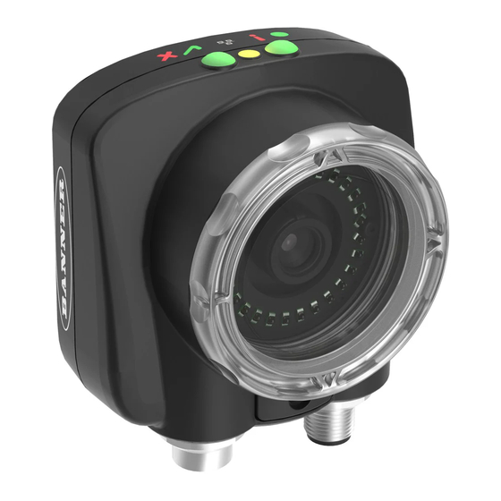
Figure 1. Features
1. Power LED
2. Pass/Fail LED
3. Ethernet I/O LED
4. Focusing Window
5. Focusing Window Locking Clip
6. Integrated Display (integrated display
models only)
24 April 2018
Green: Ready/Power
Red (blinking or steady): Error
Green (steady): Pass
Green (blinking): Error
Red: Fail
Green: Connected
Off: Disconnected
www.bannerengineering.com
178442
. The
Advertisement
Table of Contents

Related Manuals for Banner iVu Plus TG


Summary of Contents for Banner iVu Plus TG
-
Page 1: Installation Instructions
Quick Start Guide Introduction This guide is designed to help you set up and install the iVu Plus TG and Color Gen2 Image Sensors. For complete information on programming, performance, troubleshooting, dimensions, and accessories, please refer to the Instruction Manual at www.bannerengineering.com... -
Page 2: Cable Connections
Plus TG and Color Gen2 Image Sensors 2. Thread three M4 x 4 mm screws (supplied) through the bracket into the mounting holes in the bottom of the iVu. Figure 2. Mounting Bracket Mounting Holes 3. Tighten all three screws. -
Page 3: Home Screen
Plus TG and Color Gen2 Image Sensors Figure 5. System Menu Figure 4. Select Type Screen Note: Switch between Live Mode and Demo Mode any time by going to Main Menu > System > Mode. Home Screen Use the Home screen on the iVu display to monitor inspections and to configure the iVu. Typically, the part being inspected is centered on the screen with the feature of interest bounded by the Region of Interest (ROI), a rectangle as shown below. - Page 4 Plus TG and Color Gen2 Image Sensors Inspection ROI Type Sensors Area Intensity Range Area Range Motion Number of Edges Visible when Motion = Enabled Pass Count Sensitivity Rotation Blemish ROI Type Sensitivity Edge Length Range Inspection Name Properties...
- Page 5 Plus TG and Color Gen2 Image Sensors Auto Exposure Imager Mode Live System Exposure Demo Gain Trigger Save to USB Configuration Focus Load from USB External Strobe Reset to Defaults Information Internal Lock Device Connection Communications Ethernet I/O Resolution...
-
Page 6: Acquiring A Good Image
Capture the shape and form of the target object with lighting that optimizes its contrast and separates it from the background. Depending on the target, this may mean the integral ring light is not the best choice and other Banner lights should be considered. -
Page 7: Adjust The Focus On A Micro Video Lens Model
Plus TG and Color Gen2 Image Sensors 3. If needed, go to Main Menu > Imager > Auto Exposure to run the Auto Exposure routine a second time or adjust Gain and Exposure manually: • Main Menu > Imager > Gain Figure 9. -
Page 8: Adjust The Focus On A C-Mount Lens Model
Plus TG and Color Gen2 Image Sensors Adjust focus while monitoring the focus number. To ensure the best image, adjust the focus until the focus number peaks. Note: Turning the focusing window counter-clockwise focuses on closer objects, while turning the focusing window clockwise focuses on more distant objects. - Page 9 Plus TG and Color Gen2 Image Sensors 1. Go to Main Menu > Inspection > Stored Inspections and click Add New. Figure 15. Add New Screen (TG models shown) 2. Select the Sensor Type for the new inspection, and click Next.
-
Page 10: Change The Running Inspection
Plus TG and Color Gen2 Image Sensors 3. Click the yellow arrow to enter a custom inspection name, if desired. Figure 16. New Inspection Screen 4. Click Done. The newly created inspection will now be the currently running inspection. -
Page 11: Ivu Plus Communication Summary Of Ethernet And Serial
Plus TG and Color Gen2 Image Sensors iVu Plus Communication Summary of Ethernet and Serial The iVu communicates with other devices via Ethernet or a UART serial communications port (RS-232). To establish an Ethernet connection to the iVu, configure the external device with the correct IP address and TCP port. To use the serial communications connection, configure the port settings for baud rate, data bits, parity, and stop bits on the iVu to match the settings of the external device. -
Page 12: Specifications
Banner Engineering Corp. Limited Warranty Banner Engineering Corp. warrants its products to be free from defects in material and workmanship for one year following the date of shipment. Banner Engineering Corp. will repair or replace, free of charge, any product of its manufacture which, at the time it is returned to the factory, is found to have been defective during the warranty period. This warranty does not cover damage or liability for misuse, abuse, or the improper application or installation of the Banner product.
Need help?
Do you have a question about the iVu Plus TG and is the answer not in the manual?
Questions and answers