
Related Manuals for SolaX Power AELIO-P50B200


Summary of Contents for SolaX Power AELIO-P50B200
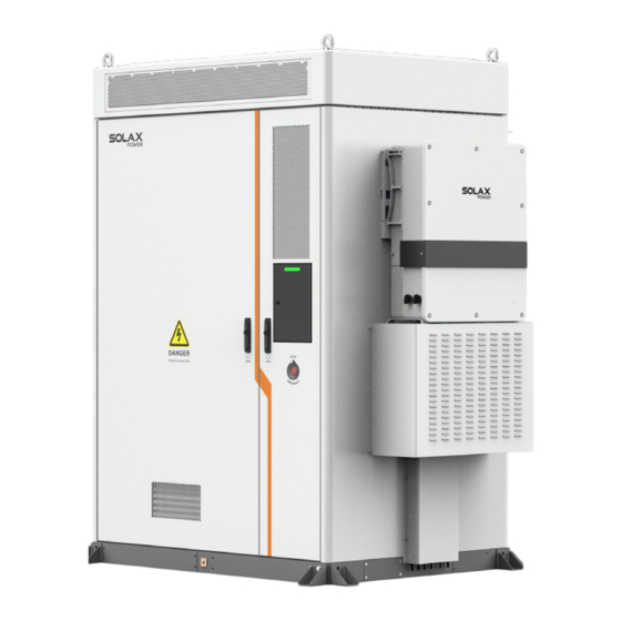
- Page 1 Air Cooling Energy Storage System AELIO-P50B200 / AELIO-P60B200 Installation Manual Version 2.0 www.solaxpower.com eManual in the QR code or at http://kb.solaxpower.com/...
-
Page 3: Table Of Contents
Table of Contents Safety ........................1 Preparation before Installation ..............9 Mechanical Installation ...................22 Electrical Connection ..................27 Power on the System ..................50 LED Indicators ....................54 System Configuration ..................56... -
Page 4: Safety
Safety General Notice 1. Contents may be periodically updated or revised. SolaX reserves the right to make improvements or changes in the product(s) and the program(s) described in this manual without the prior notice. 2. The installation , maintenance and grid-related setting can only be performed by qualified personnel who: •... - Page 5 DANGER! • According to the local laws and regulations related to high-altitude work, operators must wear PPE, e.g., a helmet, safety belt, or waist harness, when they work at heights, while the other end of the harness must connect to a secure structure to prevent fall incidents.
- Page 6 DANGER! • Only operate the inverter if it is in a technically faultless condition. Operating a faulty inverter may lead to electric shock or fire. • Do not attempt to open the enclosure without authorization from SolaX. Unauthorized opening of the enclosure will void the warranty and can result in lethal danger or serious injury due to electric shock.
- Page 7 WARNING! • Please read the document carefully before installation, operation and maintenance. • Must arrange fire-fighting equipment in advance according to the local laws, regulations, and standards while installing and commissioning the device. • Please check that there is no damage to the outer packaging before and after unpacking, and in the process of storage and transportation.
- Page 8 WARNING! • Operators must wear PPE while installation and maintenance of the device. • During operation, avoid touching any parts of the inverter other than the DC switch and LCD panel. • Never connect or disconnect the AC and DC connector while the inverter is running. •...
- Page 9 NOTICE! Transportation requirements for battery: • Relevant qualifications for the transport of dangerous goods must be obtained by the forwarding agent engaged in such businesses, and they must strictly abide by the local regulations for the transport of dangerous goods. •...
- Page 10 NOTICE! • The inverter has an integrated Residual Current Monitoring Unit (RCMU). If an external Residual Current Device (RCD) is required by local regulations, verify the type of RCD required. It is recommended to use a Type-A RCD with a rating of 300 mA unless a lower value is required by the specific local electric codes.
- Page 11 NOTICE! Cable Requirements: • When deciding the wire diameter, and connecting or wiring cables, follow the local laws, regulations, and codes to ensure safety. • When external conditions (e.g., placement method, ambient temperature, etc.) change, the cable type must be verified according to IEC-60364-5-52 or local laws, regulations and standards.
-
Page 12: Preparation Before Installation
Preparation before Installation Packing List • Battery cabinet Cabinet × 1 Cover × 4 Large cable cover × 1 Small cable cover × 1 M24 eye bolt × 4 Angle support × 4 M12 Expansion bolt × 10 Fireproof mud × 2 M6*16 Hexalobular Hexalobular key ×... - Page 13 • Inverter Inverter × 1 Mounting bracket × 1 M5 screws × 4 Cable clamp × 1 Positive battery connectors × 2 Negative battery connectors × 2 OT terminal × 1 RJ45 terminals × 7 8-pin terminal blocks × 2 M10*100 expansion Negative PV connectors Positive PV connectors...
-
Page 14: Installation Site
Installation Site +50°C 3000 m -30°C 0-100%RH Good ventilation Avoid flammable, explosive materials or Avoid corrosive Avoid sandy or dusty Avoid high temperature dust substances Avoid strong electromagnetic fields and Avoid strong vibration Avoid conductive and antenna and noise Avoid radiation magnetic dust Avoid toxic and harmful gases... - Page 15 Transportation Requirement • Forklift requirement Fork blade Fork blade 25 cm < T < 70 cm L > 1.2 m W=Width L=Length T=Thickness 80 cm < W < 160 cm • Carton fork holes Fork hole 321104016501 321104016501 321204016301 321204016401 Front view Rear view Left view...
- Page 16 Dimension • System dimensions Unit: mm Plan view 1967 1680 Front view Rear view 1200 Left view Right view • Inverter dimensions Ø16 616.0 662.0...
- Page 17 • Cabinet dimensions (Angle supports installed at front and rear sides) Unit: mm 1580 Installation position for eye bolt Fork position, Angle support Foundation Plan view 1680 1135.5 437.5 Front view Rear view 1200 1416 Left view Right view...
- Page 18 • Cabinet dimensions (Angle supports installed at left and right sides) Unit: mm 1900 Installation position for eye bolt 1680 Fork position, Angle support Foundation Plan view 1135.5 437.5 Front view Rear view 1200 Left view Right view...
- Page 19 Installation Foundation NOTICE! • There are two foundation schemes : concrete foundation and steel foundation. • Concrete foundation Angle supports installed at front and rear sides Unit: mm Foundation Angle support Cable threading hole ≥ 300 1940 Angle supports installed at left and right sides Unit: mm Foundation Angle support...
- Page 20 • Steel foundation Unit: mm 1780 1580 1760 1840 Plan view Right view 1900 Front view to fit M16 screw Cable threading hole Rear side Ø22*70 mm To secure cabinet To secure to Cable threading hole the ground Ø14*19 mm Front side...
- Page 21 Angle supports installed at front and rear sides Unit: mm Foundation Angle support 1420 1900 1420 Plan view Right view Angle supports installed at left and right sides Unit: mm Foundation Angle support Note: If the cabinet's angle supports are installed at left and right sides, the foundation's angle supports, which are designed to secure the cabinet, may not be installed.
- Page 22 Installation Space The device support the following installation options: 1. A single cabinet, see Figures 1 and 2; 2. Multiple cabinets, see Figures 3 and 4 . Unit: mm Unit: mm ≥ 1500 ≥ 1000 ≥ 400 ≥ 700 ≥ 400 ≥...
-
Page 23: Installation Tools
Installation Tools Multimeter Hammer drill (Ø18 mm) (≥ 1500 V DC) Measuring tape Utility knife Torque screwdriver (Flat-head: M2, M3, M10) (Phillips head: M2.5, M3, Torque wrench (M4~M12) Marker Rubber mallet M4, M5, M6 Wire stripper Crimping tool for RJ45 Hydraulic wire crimper Diagonal pliers Crimping tool for... -
Page 24: Conductor Cross-Section
Insulating gloves Safety boots Safety goggles Anti-dust mask Safety vest Safety helmet Additionally Required Materials Conductor No. Required Material Type Cross-section Dedicated PV cable with a voltage rating of 1000 V, a temperature PV cable 6 mm² resistance of 105 ℃... -
Page 25: Mechanical Installation
Mechanical Installation Handling • Hoisting NOTICE! • If the eye bolts are required to be installed based on the actual situation, please strictly follow the steps below. Steel pipe (Ø25-30 mm) Silicone gasket Front side Front side α ≤ 60°; α... - Page 26 • Forklift Left view Right view Front view Rear view Installation Procedure for Angle Support and Cover Note! There are totalling 4 angle supports for a cabinet. There are 2 pieces of expansion bolts and M12 screws for each angle support respectively, with a total of 8 pieces of expansion bolts and M12 screws, respectively.
- Page 27 Do not tighten fully Cabinet Cabinet D=distance 40 mm ≤ D < 50 mm Cabinet 42±4.2 N·m Ø18 mm Cabinet 95~105 mm 90° 42±4.2 N·m NOTICE! • The above-mentioned installation steps also apply to the angle supports, which are installed on both the left and right sides.
-
Page 28: Installation Of Antenna
Installation of Antenna Silicone cap Rear side of cabinet Antenna The reserved antenna port NOTICE! • The user can decide whether the reserved port connects an antenna based on the actual situation. • Regarding the other antenna port, the antenna is delivered with the accessories kit. - Page 29 Installation of Inverter 24.0 N·m 0.5 N·m 0.5 N·m 2.0±0.2 N·m...
-
Page 30: Electrical Connection
Electrical Connection Parts that Need Wiring NOTICE! • Before wiring, operators are required to learn which areas need to be conducted wiring. For details, see the following figure. Area c Area b Area a Area a Front view Rear view Wiring area Description Area a... -
Page 31: Cabinet Grounding
Cabinet Grounding The device supports grounding plate connection and PE connection. Either of them can be connected to the wiring area Area a in “Parts that Need Wiring”. Please strictly follow the steps below. • In the case of grounding plate connection Grounding plate 42±2 N·m... - Page 32 Prefabricated Inverter Cables in Battery Cabinet NOTICE! • The PE cable, Grid cable, EPS cable, battery cables, COM1 communication cables of the inverter are prefabricated in the battery cabinet, the cable outlets as shown below: COM 1 port Grid and EPS port BAT port Right view Terminals and Parts of Inverter...
- Page 33 AC Side Connection The Grid and EPS cables of the inverter outlet from the Grid and EPS port in “Prefabricated Inverter Cables in Battery Cabinet”, please strictly follow the steps below. Remove Disassemble the AC connector, replace the original sealing plugs with the five-hole sealing plugs (part P2). 5±1 N·m 5±1 N·m M4*12...
- Page 34 DC Side Connection Wire stripper Crimping tool for PV terminal Click! Click! ≤1000 V Click! Seal the unused PV terminals (+/-) on the inverter with dustproof buckles (+/-) respectively.
-
Page 35: Battery Connection
Secure the PV cables to the bracket with cable ties Battery Connection The battery cables of the inverter outlet from the BAT port in “Prefabricated Inverter Cables in Battery Cabinet”, please strictly follow the steps below. Click! -
Page 36: Communication Connection
Communication Connection COM 1 communication connection 1. Pin assignment of COM 1 terminal PARALLEL 2 PARALLEL 1 1: PARALLEL_485A 1: PARALLEL_485A 2: PARALLEL_485B 2: PARALLEL_485B 3: DATA_BUS 3: DATA_BUS 4: PARALLEL_CANH 4: PARALLEL_CANH 5: PARALLEL_CANL 5: PARALLEL_CANL 6: GND_COM 6: GND_COM 7: PARALLEL_SYNC1 7: PARALLEL_SYNC1 8: PARALLEL_SYNC2... - Page 37 2. Cable connection steps The EMS communication cable and BMS communication cable outlet from the COM 1 port “Prefabricated Inverter Cables in Battery Cabinet”, please strictly follow the steps below. * Connect the cables according to the actual function requirements. Remove Pinch both ends of the connector to remove it.
- Page 38 COM 2 communicaiton connection 1. Pin asignment of COM 2 terminal Meter/CT Ripple control Pin assignment Definition Meter/CT CT_R1_CON CT_S1_CON For CT connection CT_T1_CON METER_485A For Meter connection METER_485B CT_T2_CON CT_S2_CON For CT connection CT_R2_CON Ripple control RP_K4 GND_COM RP_K3 GND_COM For ripple control connection RP_K2...
- Page 39 Pin assignment Definition DI_2+ Reserved DI_2- Reserved for connecting the shielding layer of the cables if GND_COM there is strong interference in the surroundings. EPSBOX_RELAY_VCC 12V power supply 2. Meter/CT connection • Connecting to wire meter • Connecting to CT •...
- Page 40 • Meter connection diagram * The meter in the connection diagram is taken as an example with DTSU666. RS485 on DTSU666 2425 RS485 Grid Meter 1 E-BAR Meter 2 Power connection on DTSU666 other power generatation Grid input Output equipment •...
- Page 41 * Markings on the CTs might be R, S and T or L1, L2 and L3. Make sure to clip CT-R/CT-L1 to the L1 wire, CT-S/CT-L2 to the L2 wire, and CT-T/CT-L3 to the L3 wire. • CT connection diagram CT-L1 CT-L2 CT-L3...
- Page 42 Four-core Four-core Four-core Four-core 0.4 ± 0.1 N·m 0.4 ± 0.1 N·m For Ripple Control For DIO Click! 0.6 ± 0.1 N·m...
- Page 43 EPS Connection Wiring area Area b in “Parts that Need Wiring” must be connected EPS wires. Please strictly follow the steps below. NOTICE! • Take out the underground electrical wiring which is buried beneath the ground. α ≥ 130° α α...
- Page 44 Since the procedure for installing a terminal is same,take the L1 copper wire, for instance. (Ø15-20 mm) 50-60 mm Heat-shrink Hydraulic tubing wire Note! crimper Do not damage the TLK35-8 ring terminal conductor insulation while crimping. Heat shrink tubing Cable Do not place the Diameter Length...
- Page 45 Cover Clamp Connection area Unscrew M5 screws to remove the cover. Note: Please keep the M5 screws and cover properly. There are two options (a and b) for pulling through cables. • In the case of option a, unscrew hexalobular socket screws to remove cover.
- Page 46 12±1 N·m EPS wires 3±0.3 N·m 5±0.5 N·m Cover Clamp 1.2±0.1 N·m...
-
Page 47: Grid Connection
Grid Connection Wiring area Area c in “Parts that Need Wiring” must be connected GRID wires. Please strictly follow the steps below. α α ≥ 130° Note: Open the rear door. Please keep the keys properly. 20 mm 160-180 mm Cable Cross-sectional area Strip length... - Page 48 (Ø17-25 mm) Since the procedure for installing a terminal is 50-60 mm same,take the L1 copper wire, for instance. TLK35-8 ring Hydraulic (Ø10-15 mm) terminal wire TLK16-8 ring 30-40 mm crimper terminal Heat shrink tubing Cable Note! Diameter Length Do not damage the conductor L1/L2/L3/N: Ø17-25 mm 50-60 mm insulation while crimping.
- Page 49 M5 screw Cover Connection area Unscrew M5 screws to remove the cover. Note: Please keep the M5 screws and cover properly. There are two options (a and b) for pulling through cables. • In the case of option a, unscrew hexalobular socket screws to remove cover.
- Page 50 12±1 N·m Grid wires 3±0.3 N·m 5±0.5 N·m 12±1 N·m...
- Page 51 Note: Must clean the materials, such as metal Hook parts, screws, etc., in the cabinet after finishing wiring. M5 screw Cover 3±0.3 N·m Fireproofing Mud Installation Grid wire EPS wire Fireproof mud Fireproof mud NOTICE! Notice for fireproofing mud: • Take out the fireproof mud delivered with the cabinet and knead it into a ball shape. In the case of the low temperature, place it into warm water, of which the temperature range is between 40°C and 70 °C, with its package until it is soft.
- Page 52 Installation of Cable Cover NOTICE! • Do not install the cable cover until the all the cables are wired. Unscrew M6 hexalobular screws, with a total of 8 screws. Note: Keep these screws properly. Install the large cable cover. Install the small cable cover.
-
Page 53: Power On The System
Power on the System Regarding the detailed location of the modules in the cabinet, see following figure. Inverter Distribution box Battery pack High-voltage box For the detailed steps, see following figures. SPD MCB HVAC SPD MCB HVAC SPD MCB HVAC AC MCCB AC MCCB Distribution box... - Page 54 SPD MCB HVAC APS UPS AC MCCB Distribution box Power on/off Menu High-voltage box...
- Page 55 Note: Please properly keep the keys. Inverter Inverter...
- Page 56 Turn on AC breaker AC breaker Main breaker Emergency Power Off WARNING! • Do not press the emergency stop button except for emergencies. • Some modules inside the cabinet may still have power after pressing the emergency stop button, therefore, non-professionals are not allowed to operate them. NOTICE! If it has been pressed, the emergency stop button must be reset before starting the device.
-
Page 57: Led Indicators
LED Indicators Cabinet's LED Light LED light Status Description Solid yellow light In standby Solid green light In operation Solid red light System failure High-voltage Box's LED Light LED light Status Description Flashing green light In operation Solid green light Rely in off state Solid red light System failure... - Page 58 Battery Pack's LED Light LED light Status Description Flashing green light In operation Inverter LED Panel Operating indicator light Timely output power Power Today’s energy Today 0.0KWh Battery indicator light Battery Normal Down Error indicator light Enter Battery connection status Status or error information Battery SOC •...
-
Page 59: System Configuration
LED indicator Status Definition One of the battery terminal is connected Light on in a normal state at least. Both of the battery terminals are Battery Blinking connected are in an idle state. One of the battery terminals is Solid display connected normally at least. -
Page 60: Advance Settings
Advance Settings =======Menu======= =====Password====== ======Settings====== History Data >Settings > User Setting About >Advance Setting The initial password is 2014 which should be changed for the consideration of account security. • Safety Code ==Advance Settings==== ====Safety Code===== >Country >Safety Code Grid Parameters VDE 4105 Set the corresponding safety standards according to different countries •... -
Page 61: Ems Configuration
Inverter Screen Cover Installation It is recommended that the inverter screen cover should be installed after all settings on the inverter LCD screen are set. M4*10 1.5±0.3 N·m EMS Configuration Unlocking screen door Keyhole EMS screen Correct position Screen door Log in to the screen Username Password... - Page 62 Username Password View EMS Registration No., and then Log out. Admin EMS Registration No. ********** Sign in an admin account admin ********** Add inverter...
- Page 63 Set inverter parameters Device type COM method COM port Connected device qty Address allocation Inverter Modbus RTU COM 7 Auto inverter Modbus RTU COM 7 Auto NOTICE! • If the device connects in parallel, the number in the Connected device qty column shall be based on the actual quantity of inverters.
- Page 64 Save and pre-check Confirm SolaXCloud Download SolaXCloud Scan the QR code to download SolaXCloud App. Follow the tutorial or online documents on the SolaXCloud App to complete the configuration.
- Page 65 Technical Data • DC Side Model AELIO-P50B200 AELIO-P60B200 Max. PV input power [kW] Max. PV input voltage [V] 1000 1000 Start output voltage [V] Rated input voltage [V] MPPT voltage range [V] 160~950 160~950 No. of MPP trackers / Strings per MPP tracker...
- Page 66 • Battery Model AELIO-P50B200 AELIO-P60B200 Battery type LiFePO4 Rated battery capacity [kWh] Rated battery voltage [V] 716.8 Battery voltage range [V] 560~817.6 Discharge depth [%] Rated charge/discharge current [A] Max charge/discharge current [A] 160 (80 × 2) • General Parameter...
-
Page 67: Contact Information
Contact Information AUSTRALIA UNITED KINGDOM Unit C-D Riversdale House, Riversdale 21 Nicholas Dr, Dandenong South VIC 3175 Road, Atherstone, CV9 1FA +61 1300 476 529 +44 (0) 2476 586 998 service@solaxpower.com.au service.uk@solaxpower.com TURKEY GERMANY Fevzi Çakmak mah. aslım cd. no 88 A Am Tullnaupark 8, 90402 Nürnberg, Karatay / Konya / Türkiye Germany... -
Page 68: Warranty Registration Form
Warranty Registration Form For Customer (Compulsory) Name Country Phone Number Email Address State Zip Code Product Serial Number Date of Commissioning Installation Company Name Installer Name Electrician License No. For Installer Module ( If Any ) Module Brand Module Size(W) Number of String Number of Panel Per String Battery ( If Any ) - Page 69 SolaX Power Network Technology (Zhejiang) Co., Ltd. Add.: No. 278, Shizhu Road, Chengnan Sub-district, Tonglu County, Hangzhou, Zhejiang, China E-mail: info@solaxpower.com Copyright © SolaX Power Network Technology (Zhejiang) Co., Ltd. All rights reserved. 320102133902...
Need help?
Do you have a question about the AELIO-P50B200 and is the answer not in the manual?
Questions and answers