
Related Manuals for SolaX Power XRSD-1C


Summary of Contents for SolaX Power XRSD-1C
- Page 1 Rapid Shutdown XRSD-1C/XRSD-2C XRSD-Core Kit User Manual Version 0.0 www.solaxpower.com eManual in the QR code or at http://kb.solaxpower.com/...
- Page 3 No part of this manual may be reproduced, transmitted, transcribed, stored in a retrieval system, or translated into any language or computer language, in any form or by any means without the prior written permission of SolaX Power Network Technology (Zhejiang) Co., Ltd.
- Page 4 About This Manual Scope of Validity This manual is an integral part of the SolaX XRSD-1C/2C and XRSD-Core Kit. It describes the detailed information , installation,and usage of the product. Please read it carefully before operating. XRSD-1C XRSD (SolaX Rapid Shutdown Device)
- Page 5 Conventions The symbols that may be found in this manual are defined as follows. Symbol Description Indicates a hazardous situation which, if not avoided, DANGER will result in death or serious injury. Indicates a hazardous situation which, if not avoided, WARNING could result in death or serious injury.
-
Page 6: Table Of Contents
Table of Contents Safety ......................1 1.1 General Safety ........................1 1.2 Safety Instructions ......................2 Product Overview ..................4 2.1 System Description ......................4 2.2 XRSD ............................5 2.3 XRSD-Core Kit ........................6 2.4 Symbols on the Device ....................7 Installation ....................8 3.1 Safety Precautions ......................8 3.2 Scope of Delivery.......................10 3.3 Tools Requirement ......................12 3.4 XRSD Installation ........................14 3.5 XRSD-Core Kit Installation .....................20... -
Page 7: Safety
Safety General Safety Safety precautions must be strictly observed and followed to reduce the risk of personal injury and ensure a safe installation. Before installing the device, carefully read, fully understand, and strictly follow the detailed instructions of the user manual , related sections of your inverter manual, and other regulations. -
Page 8: Safety Instructions
Safety Safety Instructions Please read these instructions carefully, and use this product correctly and safely. After reading, please keep these instructions in a safe place DANGER! • When exposed to sunlight, high DC voltage will be generated by PV modules. Death or lethal injuries will occur due to electric shock. •... - Page 9 Safety WARNING! • Do not touch the XRSD when it is running. Surface high temperature may cause burns or personal injury. • Do not attempt to repair the device if it is not working properly, please contact the SolaX Customer Support team. Any attempt to repair the XRSD will automatically void the warranty.
-
Page 10: Product Overview
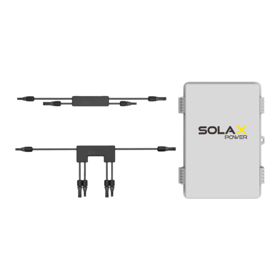
Safety System Description XRSD-Core Kit XRSD-1C Figure 1-1 Enables rapid shutdown XRSD-2C Figure 1-2 Enables rapid shutdown and monitoring (Be equipped with SolaX Pocket WIFI+LAN) -
Page 11: Xrsd
XRSD XRSD-1C XRSD-2C As part of the SolaX rapid shutdown solution for PV system, XRSD-1C can be connected to one PV module while XRSD-2C can be connected to two. Highlights • Meets NEC2017&NEC2020 • Lower power consumption and 690.12 requirements... -
Page 12: Xrsd-Core Kit
Safety XRSD-Core Kit The XRSD-Core Kit, in tandem with XRSD,forms a crucial segment of the SOLAX rapid shutdown system. It includes an outdoor enclosure, an 85~264V power supply, a transmitter, a SolaX module-level monitoring dongle (optioanl), and one core (two cores are optional). Highlights •... -
Page 13: Symbols On The Device
Safety Symbols on the Device The information on the device includes technical data and serial number of the device. Safety instructions on the label are listed and explained below : Table 1-1 Description of symbols Symbol Description Danger of high voltages. Danger to life due to high voltages in the inverter! Danger. -
Page 14: Installation
Installation Safety Precautions • Do not attempt to install in inclement weather. • Only qualified personnel can perform the mechanical installation. • Perform all electrical installations in accordance with local codes. • Be equipped with individual protective tools and insulated tools when installing the XRSD and XRSD-Core Kit. - Page 15 Installation • After installing XRSD and XRSD-Core Kit, place the rapid shutdown system label within 1m of the emergency stop button or AC disconnect. Figure 2-1 Rapid shutdown system label...
-
Page 16: Scope Of Delivery
Installation Scope of Delivery XRSD XRSD-1C XRSD-2C Rapid shutdown device * Refer to the actual purchase quantity. XRSD-Core Kit... - Page 17 Installation Table 2-1 XRSD-Core Kit Packing list Item Description Quantity Remark 1 pcs Outdoor enclosure 4 pcs Mounting lugs 4 pcs For wall-mounting instalation Round head screws Plastic wall anchor & 4 pairs Self-Tapping screw 1 pcs DIN35 rail M4.8*L10 screw 2 pcs For securing DIN35 rail Clamps...
-
Page 18: Tools Requirement
Installation Tools Requirement Installation tools include but are not limited to the following recommended ones. If necessary, use other auxiliary tools on site. Torque screwdriver Step drill bit Measuring tape Utility knife (Phillips head: PH2) Hammer drill Marker Spirit level Rubber mallet (drill bit: Ø10 mm) Wire stripper... - Page 19 Installation Additionally Required Materials Table 2-2 Additionally required wires Required Material Type Quantity PV cable According to the inverter type MC4 PV Connector match with PV cable of inverter M12(for power cable port) 1 pcs M12(for Ethernet cable port) 1 pcs Waterproof connectors 2 pcs with corrugated pipe...
-
Page 20: Xrsd Installation
XRSD-1C Output+ Output- Input- Input+ Figure 2-2 XRSD-1C terminal Step 1: Install XRSD on the frame of the PV module with mounting brackets. Mounting Brackets Figure 2-3 Buckle XRSD on the PV module frame. - Page 21 You can use the DC extension cabel if necessary. Figure 2-4 Connect PV modules to XRSD inputs Step 3: Use a multimeter to measure the XRSD-1C output voltage. The output voltage should be 0.2~1.5V. 0.2~1.5V...
- Page 22 Installation Step 4: Connect the output of two adjacent XRSDs together. Figure 2-6 Connect XRSD outputs in series. Step 5: Remove the serial barcode sticker and stick it on the corresponding position on the installation map, which is used to model the physical layout of the roof module.
- Page 23 Output- + INPUT - + INPUT - Input+ Input- Input+ Input- Figure 2-8 XRSD-1C terminal Step 1: Install XRSD on the frame of the PV module with mounting brackets. Mounting Brackets Figure 2-9 Buckle XRSD on the PV module frame.
- Page 24 Installation Step 2: Connect modules to XRSD inputs. Each XRSD must have a PV module connected to its inputs. You can use the DC extension cabel if necessary. +OUTPUT OUTPUT- + INPUT - + INPUT - +OUTPUT OUTPUT- + INPUT - + INPUT - Figure 2-10 Connect PV modules to XRSD inputs Step 3: Use a multimeter to measure the XRSD-2C output voltage.
- Page 25 Installation Step 4: Connect the output of two adjacent XRSDs together. +OUTPUT OUTPUT- +OUTPUT OUTPUT- + INPUT - + INPUT - + INPUT - + INPUT - Figure 2-12 Connect XRSD outputs in series. Step 5: Remove the serial barcode sticker and stick it on the corresponding position on the installation map, which is used to model the physical...
-
Page 26: Xrsd-Core Kit Installation
Installation XRSD-Core Kit Installation XRSD-Core Kit box drilling Step 1: Drill holes on the sides of the enclosure by using the drilling template. For detailed size please refer to “2.6 Conduit Drilling Guide” Remove burrs after drilling holes. Step 2: Install the waterproof connectors to ensure the safety of the box. /M32 Figure 2-14 Install waterproof connectors Step 3: Fix the mounting lugs with round head screws at the four corners of the... - Page 27 Installation Box inside installation 12V- 12V+ WIFI +12V PLC1 PLC2 1 Clamp 2 Power supply 3 Transmitter 4 Clamp 5 Pocket WiFi+LAN (Optional) 6 Core1 7 Core2 (Optional) Connection diagram * The illustrations in this manual all include an optional monitoring dongle.
- Page 28 Installation Step 4: Fix the DIN rail onto the second row from the top. M4.8*L10 3 N·m Figure 2-16 Fix DIN rail Step 5: Mount AC power supply, transmitter, SolaX Pocket WiFi+Lan, and cores on DIN rail in the following order. Fix a clamp at the left ends of the rail, then use a one-screwdriver to cock the edge of the clamp and snap it into the rail slot.
- Page 29 Installation 2) Pull down the bottom latch of the power supply. Attach the power supply to the rail and push the latch back. Push back Pull down Figure 2-18 Fix power supply 3) Pull down the latch of transmitter. After fixing the transmitter to the rail, push the latch back. Install anothor clamp next to the transmitter.
- Page 30 Installation 4) Assemble the module according to the SolaX Pocket WiFi+LAN Series Installation Manual , and then mount it on the Din rail. Insert the M4*L16 screws into the holes on both sides of the pipe strap, then use a cross-screwdriver to fix the screws on the rail. M4*16 0.5 N·m Figure 2-20 Fix monitoring dongle...
- Page 31 Installation Step 6: Connect the emergency stop switch wire to the power supply and fix it to the rail. Then secure the wires with a flat-head screwdriver. red/black wire — Power supply "+"/"-" port plastic terminal — Transmitter "+12V-GND" port ( Align the red wire with the "+12V"...
- Page 32 Installation Wall mounting Installation SOLAX Inverter location Recommended distance ≤ 150 mm Figure 2-24 Recommended installation distance Step 8: Lock the XRSD-Core Kit box. Align the enclosure horizontally on the wall with spirit level: adjust the enclosure until the bubble stays in the middle. Mark the position of the drill holes.
- Page 33 Installation Step 9: Set the enclosure aside and drill holes.(Drill bit:Ø10; Depth:60-80mm) Insert the expansion bolt into holes by using a rubber mallet. Ø10 mm drill bit 90° Depth 60-80 mm Figure 2-26 Drill the holes Step 10: Use a torque wrench to secure the enclosure to the wall with expansion bolts.
- Page 34 Installation Wire connection DANGER! Press the emergency stop button to cut off the AC power before wire connection. Step 11: Pull the PV cable through a corrugated pipe into the box. Figure 2-28 Pull the PV cable through corrugated pipe Step 12: Connect wires to N,L port of power supply from grid or inverter.
- Page 35 Installation Dual Core AC wires PV cables Figure 2-30 Dual cores-cable connect NOTICE! If the number of PV strings exceeds 10, do not pass PV cable (-) through the box, connect it to the inverter from outside the box. NOTICE! If you select the optional monitoring dongle and a LAN connection is used, pull another side of the network cable out of the box, crimp RJ45 connector and connect...
- Page 36 Installation Step 14: Make the MC4 connector for PV cables. Click! Thread the PV cable through swivel nut and insert into the PV connector. A "Click" will be heard if it is connected correctly. Gently pull the cable backwardto ensure firm connection. Tighten the swivel nut clockwise.
- Page 37 Installation Commissioning Step 1: Release the emergency stop button to turn on the AC power. Figure 2-34 Twist emergency stop button Step 2: Turn the DC switch of the inverter to ON positon. Figure 2-35 Turning on the DC switch Step 3: After waiting for about 1 minute, please check the voltage of the series circuit displayed on the inverter.
-
Page 38: Conduit Drilling Guide
Installation Conduit Drilling Guide Single Core Dual Core Ethernet Ethernet cable port cable port NOTICE! Ethernet cable port is only required when the monitoring dongle (optional) is selected and a LAN connection is used. Ø12 Ø12 2×Ø34 2×Ø34 2×Ø26 2×Ø26 Figure 2-36 Drilling Guide for 1"and .75'' Conduit... -
Page 39: Remote Monitoring
Remote monitoring * The following content applies to the XRSD-Core Kit with monitoring dongle. SolaxCloud is an intelligent management platform for home energy, which integrates energy efficiency monitoring, device management, data security communication and other integrated capabilities. The XRSD-Core Kit, equipped with Pocket WiFi+LAN, can upload operation data to the SolaX Cloud through a WiFi or LAN network connection. -
Page 40: Downloading And Installing Solax Cloud App
Remote monitoring * The screen shots hereupon are for reference only. You can update App as needed. Downloading and installing SolaX Cloud App Select and scan the QR code below to download SolaX Cloud APP. You can also find the QR codes at the top left of the login page of www.solaxcloud.com. In addition, you can search with the key word SolaxCloud in Apple Store or Google Play to download it. -
Page 41: Site Creation And Wi-Fi Configuration
Remote monitoring Site creation and Wi-Fi configuration Creat Site Tap + to create your site.Allow SolaxCloud to access your system location, fill in site name (self-defined), system size (For the system size, please check the information with the installer), choose the following settings according to actual situations.Tap Next to add device. - Page 42 Remote monitoring Add XRSD-Core Kit Pocket WiFi+LAN Scan or enter the QR code on , tap Next. < Add device Select Wireless Device networking Add site Network configure *Registration No. Add device Back Next Figure 3-4 Add XRSD Core Kit Connect via Wi-Fi Tap arrow to select your local network from the list.
-
Page 43: Add Xrsd
Remote monitoring Add XRSD To view an existing site, select one of the systems in the list. To add XRSD, tap the added Core Kit > Auto find | Add RSD < Power Station Details Site Site name: Site1 System Size(kW):*** Country and region:*** Site List Timezone: ***... - Page 44 Remote monitoring Enter each XRSD page, you can see the device details and PV panel‘s current, volatage, power, temperature. < Device Details Device Name: 60D0110***1121 Online Device Type: XRSD Specifications: XRSD-2C Entry Time: yyyy-MM-dd HH:mm:ss Remote Settings Select date 2023-11-25 2023-11-26 PV1 PV2 2,500...
-
Page 45: Layout Settings
Remote monitoring Layout Settings Place the modules according to the physical layout: an exact map will help you understand the positon of XRSD and each PV panel's power. In addition, this will facilitate future maintenance work. Set PV array rules Enter power station page, select Layout>Edit now>Array rules. - Page 46 PV power of the current day or history. Power(W) Select a PV to check the PV details, which include: the serials number port 1 represent XRSD-1C,2 represent XRSD-2C Device type XRSD Connection status Network status Normal/Exception Alarm status Normal/Exception(i.e over current)
- Page 47 Remote monitoring Data Current, voltage, and power values at now Graphics Current, voltage, and power trend charts so far < Layout Hint: Power(W) 02.18 The PV array rules (horizontal/vertical, tilt angle) will affect the display of PV here. The legend represents that the PV display is vertical and the tilt angle is 0.
-
Page 48: Rapid Shutdown Methods
Rapid Shutdown methods XRSD can be shutdown automatically or manually. For modify the automatic shutdown setting value, please refer to Remote setting (P38). Automatic shutdown Automatic shutdown will occur if any of the following conditions are met: • Over temperature When the temperature sensor on the XRSD detects ambient temperature is over the set value (Default: 85°C) •... -
Page 49: Technical Data
Technical Data • XRSD Model XRSD-1C XRSD-2C Electrical Data Input voltage range 8-80V 8-80V / 8-80V Output voltage range 8-80V 16-160V Max. PV input current Max. short circuit current Recommended fuse rating Maximum system voltage 1500V 1500V Mechanical Dimensions(W x D x H) - Page 50 Technical Data • XRSD-Core Kit Model XRSD-Core Kit Electrical Data Power Supply Input Voltage 85-264Vac 12Vdc ( ± 2%) Transmitter Input Voltage Transmitter Input Current Core Max. Number of Configure Core Max. Current per Core 150A Max. String Voltage 1500Vdc Diameter ~31 (inner) /52mm (outer) Max.
-
Page 51: Appendix
Appendix... - Page 53 Contact Information UNITED KINGDOM AUSTRALIA Unit C-D Riversdale House, Riversdale 21 Nicholas Dr, Dandenong South VIC 3175 Road, Atherstone, CV9 1FA +61 1300 476 529 +44 (0) 2476 586 998 service@solaxpower.com service.uk@solaxpower.com TURKEY GERMANY Fevzi Çakmak mah. aslım cd. no 88 A Am Tullnaupark 8, 90402 Nürnberg, Karatay / Konya / Türkiye Germany...
- Page 55 SolaX Power Network Technology (Zhejiang) Co., Ltd. Add. : No. 278, Shizhu Road, Chengnan Sub-district, Tonglu County, Hangzhou, Zhejiang, China E-mail : info@solaxpower.com www.solaxpower.com 320101080200 Copyright © SolaX Power Network Technology (Zhejiang) Co., Ltd. All rights reserved.
Need help?
Do you have a question about the XRSD-1C and is the answer not in the manual?
Questions and answers