SolaX Power X1-IES Series User Manual
Hide thumbs
Also See for X1-IES Series:
- Installation manual (179 pages) ,
- Installation manual (184 pages)

Related Manuals for SolaX Power X1-IES Series


Summary of Contents for SolaX Power X1-IES Series
- Page 1 X1-IES User Manual X1-IES-2.5K / X1-IES-3K / X1-IES-3.7K X1-IES-4.6K/ X1-IES-5K X1-IES-6K / X1-IES-8K www.solaxpower.com...
- Page 3 No part of this manual may be reproduced, transmitted, transcribed, stored in a retrieval system, or translated into any language or computer language, in any form or by any means without the prior written permission of SolaX Power Technology (Zhejiang) Co., Ltd. Trademarks and other symbol or design (brand name, logo) that distinguishes the products or services offered by SolaX has been trademark protected.
- Page 4 Note: "X1-IES system" is a residential single-phase photovoltaic storage hybrid inverter system. "X1-IES series inverter" (inverter for short) refers to the energy storage inverter that supports photovoltaic grid-connected. “3K"means rated output power of 3kW. "T-BAT-SYS-HV-S50E" (T-BAT-SYS for short) is the name of battery system.
- Page 5 "Series box" is used to connect the two towers through wiring. It is installed on the top battery module of the expansion battery tower and inside the "cover". Target Group The installation, maintenance and grid-related setting can only be performed by qualified personnel who •...
-
Page 6: Table Of Contents
Table of Contents Safety ......................1 1.1 General Safety ........................1 1.2 Safety Instructions of PV, Inverter, Grid and Battery ..........2 1.2.1 Safety Instructions of PV ..................2 1.2.2 Safety Instructions of Inverter ................2 1.2.3 Safety Instructions of Utility Grid ..............3 1.2.4 Safety Instructions of Battery (T-BAT-SYS) ............3 1.3 Additional Safety Instructions ..................7 Product Overview ..................9 2.1 System Description ......................9... - Page 7 6.1 Floor Mounting ........................57 6.2 Wall Mounting ........................75 6.2.1 Battery Capacity Expansion ................88 Electrical Connection ................89 7.1 System Diagram .........................89 7.2 Electrical Connection on the Battery (T-BAT-SYS) ...........90 7.2.1 Details of Cables ....................90 7.2.2 Wiring Procedure ....................91 7.2.3 Installation of Cover ....................97 7.3 Electrical Connection on the Inverter .................98 7.3.1 Wiring Sequence ....................98...
- Page 8 10.3 Operation Guide on SolaX Cloud Wed ...............172 Troubleshooting and Maintenance ............173 11.1 Troubleshooting .........................173 11.2 Maintenance ........................184 11.2.1 Maintenance routines ..................184 11.2.2 Upgrading Firmware ....................186 Decommissioning ..................188 12.1 Disassembling the X1-IES system..................188 12.2 Packing the X1-IES system ....................193 12.3 Disposing of the X1-IES system ..................193 Technical Data ..................194...
-
Page 9: Safety
Safety General Safety The X1-IES system has been meticulously designed and thoroughly tested to comply with all relevant state and international safety standards. Nevertheless, like all electrical and electronic equipment, safety precautions must be observed and followed during the installation of the X1-IES system to minimize the risk of personal injury and ensure a safe installation. -
Page 10: Safety Instructions Of Pv, Inverter, Grid And Battery
Safety Safety Instructions of PV, Inverter, Grid and Battery Save these important safety instructions. Failure to do so may result in damage to the X1- IES system and injury or even loss of life. 1.2.1 Safety Instructions of PV DANGER! Potential risk of lethal electrical shock associated with the photovoltaic (PV) system •... -
Page 11: Safety Instructions Of Utility Grid
Safety WARNING! Potential danger of scalding due to the hot enclosure of the inverter • Avoid touching the inverter while it is running, as it becomes hot during operation and may cause personal injuries. WARNING! • The series inverter should be coupled with a high voltage battery. When handling the battery, follow all the safety instructions of the manufacturer. - Page 12 Safety • Do not install the battery module in places where flammable and combustible materials are stored, and in which an explosive atmosphere is present; • The battery module wiring must be carried out by qualified personnel; • Battery module must be serviced by qualified personal; •...
- Page 13 Safety • DO NOT charge or discharge a damaged battery module; • DO NOT dispose of the battery module in a fire. It may cause leakage or rupture; • DO NOT mix different types or makes of the battery module. It may cause leakage or rupture, resulting in personal injury or property damage.
- Page 14 Safety • DO NOT use the submerged battery module again, and contact the qualified personnel for assistance. • DO contact SolaX immediately for assistance if the user suspects that the battery module is damaged. WARNING! • Do not crush or impact battery; make sure dispose of it according to relevant safety regulations.
-
Page 15: Additional Safety Instructions
Safety Additional Safety Instructions Surge protection devices (SPDs) for PV installation DANGER! • Over-voltage protection with surge arresters should be provided when the PV power system is installed. The grid connected inverter is fitted with SPDs in both PV input side and MAINS side. - Page 16 Safety PE Connection and Leakage Current All inverters incorporate a certified internal Residual Current Monitoring (RCM) in order to protect against possible electrocution and fire hazard in case of a malfunction in the PV array, cables or inverter. There are 2 trip thresholds for the RCM as required for certification (IEC 62109-2:2011).
-
Page 17: Product Overview
Product Overview System Description System Overview Solax Cloud Dongle Grid Breaker X1-IES system E-BAR CT/Meter BAT+ BAT- EPS Loads Loads S olax EV Charger ! Adapt Box Datahub Communication line 485 line Figure 2-1 System overview diagram X1-IES system The X1-IES system is an energy storage system that integrates the inverter and T-BAT-SYS into one. - Page 18 Product Overview Inverter The inverter is a transformerless single-phase PV grid-connected inverter which is designed to convert the direct current generated from the PV modules into grid- compatible AC current and feeds the AC current to the utility grid or store in the batteries for future use.
-
Page 19: Supported Power Grid
Product Overview Supported Power Grid There are different ways of wiring for different grid systems. Three grid types, TT / TN-S / TN-C-S are shown as below: Figure 2-2 Supported power grid TT TN-S Figure 2-3 Supported power grid TN-S TN-C-S Figure 2-4 Supported power grid TN-C-S... -
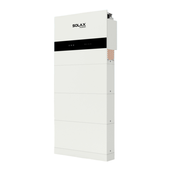
Page 20: Appearance
Product Overview Appearance OLED panel Type label DC switch, Button Upgrade/Dongle port Grid&EPS port PV port Communication connection area Electrical connection Button, area of Switch T-BAT-SYS Battery module Battery module Battery module Base Figure 2-5 Apprearance of Battery (T-BAT-SYS) and Inverter Table 2-1 Desciption of appearance of Battery (T-BAT-SYS) and Inverter Item Description... - Page 21 Product Overview Item Description PV connection Connect PV modules. area Communication Including CT/Meter port, communication port. connection area Power on or off the battery system. Please refer to 2.3.3 Ports of Button, Switch Battery BMS (TBMS-MCS0800E)P for details. Electrical Including B+/B- ports, communication port, heat port, grounding connection area port.
-
Page 22: Dimensions
Product Overview 2.3.1 Dimensions • Dimension of Inverter 210 mm 717 mm Figure 2-6 Dimension of Inverter • Dimension of Battery (T-BAT-SYS) Figure 2-7 Dimension: BMS (TBMS-MCS0800E) Figure 2-8 Dimension: Battery module (TP-HS50E) - Page 23 Product Overview Figure 2-9 Dimension: Base 91.5 Figure 2-10 Dimension: Series box...
-
Page 24: Control Panel
Product Overview 2.3.2 Control Panel • Control Panel of Inverter Status or error information OLED screen Timely output power Power Daily generated enengy 0.0KWh Today Battery Left capacity of battery energy Normal Operating indicator light ESC Up Down Enter Battery indicator light Error indicator light Figure 2-11 Control Panel of Inverter * Please refer to the actual product for the color of the LCD screen. - Page 25 Product Overview Table 2-3 Definition of keys Definition ESC key Exit from the current interface or function Up key Move the cursor to the upper part or increase the value Down key Move the cursor to the lower part or decrease the value Enter key Confirm the selection Note:...
- Page 26 Product Overview • Control Panel of Battery (T-BAT-SYS) The power indicators show the current battery percentage. There are five indicators on the BMS, one status light and four SoC power indicators. Status 100% Light HEAT SOC1 SOC2 SOC3 SOC4 Figure 2-12 Control Panel of Battery (T-BAT-SYS) Table 2-4 Definition of indicators of Battery (T-BAT-SYS) Status Description...
- Page 27 Product Overview Warning In case of warning, the status light will flash yellow light for 1 second, and then turn off for 4 seconds. Black Start For details, please refer to 2.3.2 Black Start. Table 2-5 Indicator information while charging SoC value Status light SoC1...
- Page 28 Product Overview Communication loss of inverter Flash Flash Communication loss of battery module Flash Flash NOTICE! In case of pressing and holding BMS button, there are two circumstances as follows: • Press and hold BMS button for more than 5 seconds but less than 20 seconds, the system will enter a startup mode of inverter.
-
Page 29: Ports
Product Overview 2.3.3 Ports • Ports of Inverter Figure 2-13 Ports of Inverter Table 2-8 Description of ports of Inverter Item Description DC switch Switch button Port for Upgrading and Communication module connection. Communication module includes WiFi, LAN and 4G (optional). Ground connection port Grid and EPS Port PV connection port... - Page 30 Product Overview • Ports of Battery (T-BAT-SYS) BMS (TBMS-MCS0800E) HEAT Left side Right side Figure 2-14 BMS (TBMS-MCS0800E) Table 2-9 Description of ports Item Description The hot-plug interface is connected to the inverter. The hot-plug interface is connected to the battery module. BAT BUTTON: Start system.
- Page 31 Product Overview Item Description HEAT: Connect the HEAT port of the series box (if any), or a short-circuit plug must be inserted into the port. DIP Switch A DIP Switch is equipped on the BMS. After opening HEAT Figure 2-15 DIP Switch Table 2-10 Definition of DIP switch Description DIP Switch 1...
- Page 32 Product Overview Battery Module (TP-HS50E) A hot-plug interface that is connected to the bottom of the battery module or the BMS. A hot-plug interface that is connected to the bottom of the battery module or the base. Figure 2-16 Details: Battery module (TP-HS50E) Base A hot-plug interface that is connected to the bottom of the battery module.
- Page 33 Product Overview Series Box The series box shall be installed in case the battery modules purchased exceed 4 sets (including 4). Figure 2-18 Details: Series box Table 2-11 Description of ports Item Description GND: Connect to the grounding port of the BMS. COM: Connect to the COM port of the BMS.
-
Page 34: Symbols On The Label
Product Overview 2.3.4 Symbols on the Label Table 2-12 Description of symbols Symbol Description CE mark. The inverter complies with the requirementsof the applicable CE guidelines. TUV certified. UKCA mark. The inverter complies with the requirements of the applicable UKCA guidelines. - Page 35 Product Overview Symbol Description Keep the battery system away from children. Keep the battery system away from open flames or ignition systems. Do not dispose of the battery module together with household waste. The battery system must be disposed of at a proper facility for environmentally-safe recycling.
-
Page 36: Working Principle
Product Overview Working Principle 2.4.1 Working mode The inverter has two configurable working periods: allowed discharging period and forced charging period. For how to set the two working periods, please refer to 9.6.1 User Settings to set the working modes. The default value of allowed discharging period is 00:00~23:59, and the default value of forced charging period is 00:00~00:00(closed in default). - Page 37 Product Overview Feed-in Priority The feed-in priority mode is suitable for areas with high feed-in subsidies. The power of PV will supply the loads first, and surplus power will feed into the grid, then the remaining power will charge the battery. Priority: Loads >...
- Page 38 Product Overview Peak shaving mode Peak shaving mode is set for leveling out peaks in electricity use. The system is intelligently controlled to ensure charging takes place during off-peak hours and discharging occurs during peak hours. Power Peak Shaving Mode (Assu ming p eak p ower from 7: 00 to 9: 00 and from 18:00 to 23:00) Battery powers the load I dea: Leveling out peaks in electricity use...
- Page 39 Product Overview TOU mode In the TOU mode, different working modes, i.e Self-use, Charging, Discharging, Peaking shaving and Battery off can be set for different time periods in accordance with actual needs and environment conditions through SolaX Cloud App or Web. The day can be divided into up to 24 time slots, and the minimum time slot is 15 minutes, independent working mode can be set for each time slot.
-
Page 40: Circuit Diagram
Product Overview 2.4.2 Circuit Diagram The inverter is equipped with multi-channel MPPT for DC input to ensure maximum power even under different photovoltaic input conditions. The inverter unit converts DC into AC that meets the requirements of the power grid and feeds it into the power grid. The lightning arrester at AC / DC side can realize the function of surge protection. - Page 41 Product Overview Diagram A: N line and PE line are separated from each other, and the common load is connected to the EPS port; (For most countries) Dongle Grid X1-IES system Main Breaker Meter/CT … E-BAR … … EPS Loads Loads …...
- Page 42 Product Overview Diagram B: N line and PE line are combined together, and the common load is connected to the EPS port; (Apply to Australia) Dongle Grid X1-IES system Main Breaker Meter/CT … E-BAR … … Loads EPS Loads … …...
-
Page 43: Micro Grid
X1-IES series inverters stimulate the grid to active on-grid inverter during off- grid. By connecting on-grid inverter to the EPS port of the X1-IES series inverter, the X1-IES series inverter is able to use PV or battery energy to active on-grid inverter when utility lost. -
Page 44: Transportation And Storage
Transportation and Storage Transportation and Storage If the X1-IES system is not put into use immediately, the transportation and storage requirements needs to be met: Transportation • Observe the caution signs on the packaging of the device before transportation. • Pay attention to the weight of the device. -
Page 45: Preparation Before Installation
Preparation before Installation Selection of Installation Location The installation location selected for the X1-IES system is quite critical in the aspect of the guarantee of machine safety, service life and performance. • It has the IP66 ingress protection, which allows it to be installed outdoor; •... - Page 46 • Install the device 500 meters away from sea and at the place where the sea breeze does not directly hit. Sea breeze Inverter 300m 500m 1,000m Over 1,000m Figure 4-1 Recommended installation position Sea breeze Inverter 300m 500m 1,000m Over 1,000m Figure 4-2 Incorrect installation position...
-
Page 47: Installation Options
Preparation before Installation 4.1.2 Installation Options NOTICE! • X1-IES system inverter matches 1~4 battery modules. It is suitable for "option A/B/C/ D" in one tower and "option E/F" in two towers. • Wall mounting is recommended. • Up to three battery modules in one tower is recommended. When the installation space is limited, four battery modules in one tower can be chosen. - Page 48 Preparation before Installation Two Towers To Towers 300 mm 300 mm Option E Option F Figure 4-4 Installation option for two towers Table 4-13 Components of different options Option A Option B Option C Option D Option E Option F Left tower Right tower Left tower...
- Page 49 Preparation before Installation Net weight and dimension of X1-IES system Table 4-14 Net weight and dimension of one tower Option A Option B Option C Option D Net Weight (kg) 87.2 134.2 181.2 228.2 Dimension 730*908*210 730*1226*210 730*1544*210 730*1862*210 (mm) Table 4-15 Net weight and dimension of two towers Option E Option F...
-
Page 50: Installation Carrier Requirement
Preparation before Installation 4.1.3 Installation Carrier Requirement The mounting location must be suitable for the weight and dimension of the product and the support surface for installation must be made of a non-flammable material. • Solid brick/concrete, or mounting surface with equivalent strength; •... -
Page 51: Clearance Requirement
Preparation before Installation 4.1.4 Clearance Requirement To guarantee proper heat dissipation and ease of disassembly, the minimum space around the X1-IES system must meet the standards indicated below. For installations with two towers, make sure to leave a minimum space of 30 cm between each system and 30 cm from the ceiling. -
Page 52: Tools Requirement
Preparation before Installation Tools Requirement Installation tools include but are not limited to the following recommended ones. If necessary, use other auxiliary tools on site. Hammer drill Multimeter Measuring tape Utility knife Flat-head Marker Cross screwdriver screwdriver Allen key Crimping tool Crimping tool Crimping tool for PV terminal... - Page 53 Preparation before Installation Safety gloves Safety boots Safety goggles Anti-dust mask Torque wrench (M4) Diagonal plier...
-
Page 54: Additionally Required Materials
Preparation before Installation Additionally Required Materials • Additionally Required Materials of Inverter Table 4-18 Additionally required wires of Inverter Conductor Required Material Type Cross-section Dedicated PV wire withstand PV wire 6 mm² voltage 600 V Communication Network cable CAT5E 0.2 mm² wire Additional PE Conventional yellow and green... - Page 55 Preparation before Installation • Additionally Required Materials of Battery (T-BAT-SYS) Table 4-21 Additionally required wire of T-BAT-SYS Required Material Type Diameter External diameter: over Protective pipe Corrugated pipe 67.2 mm...
-
Page 56: Unpacking And Inspection
Unpacking and Inspection Unpacking and Inspection The number of cartons will be different due to different modes of mounting. Therefore, please check whether the number of cartons received are correct before unpacking. For details, please refer to the following table. Table 5-1 Number of cartons One Tower Two Towers... - Page 57 • Unpacking the BMS and battery module according to the following figures. If there are other cartons, such as the base support carton, and series box carton, the unpacking procedure can also be referred to the following figures. Figure 5-2 Unpacking the BMS Figure 5-3 Unpacking the battery module •...
-
Page 58: Scope Of Delivery
Unpacking and Inspection Scope of Delivery • Packing list of Inverter Expansion tubes, Self- Inverter Bracket Positioning cardboard tapping screws Positive & Negative PV connector Waterproof connector Positive & Negative Dongle with RJ45 Document PV pin contact AC terminal Ferrules for AC terminal AC terminal tool M5*14 screws M5*10 screws... - Page 59 Unpacking and Inspection Item Quantity Document 1 pc Dongle 1 pc 2 pairs for 3kW~3.7kW inverters Positive & Negative PV connector / pin contact 3 pairs for 4.6kW~8kW inverters AC terminal 1 pc Ferrules for AC terminal * 5 pcs of per type AC terminal tool 1 pair M5*14 screw...
- Page 60 Unpacking and Inspection • Packing list of T-BAT-SYS BMS (TBMS-MCS0800E) Expansion bolt Angle bracket M5*14 Phillips cheese Tapping screw Adjustable bracket Base head screw System performance Expansion screw Rotation wrench label Document Table 5-3 Packing list of BMS Item Quantity 1 pc Base 1 pc...
- Page 61 Unpacking and Inspection Battery Module (TP-HS50E) M5*14 Phillips cheese Document Battery module head screw Table 5-4 Packing list of battery module Item Quantity Battery module 1 pc M5×14 Phillips cheese head screw 2 pcs Document 1 pc Series Box (For two towers only ) Expansion bolt Angle bracket Series Box...
- Page 62 Unpacking and Inspection Item Quantity Expansion bolt 6 pcs Tapping screw 4 pcs M5×14 Phillips cheese head screw 12 pcs Expansion screw 2 pcs Power cable (black) 1 pc Power cable (red) 1 pc Communication cable 1 pc Heater cable 1 pc Grounding cable 1 pc...
-
Page 63: Mechanical Installation
Mechanical Installation Mechanical Installation One tower Two towers X1-IES system should be installed vertical to the ground. Figure 6-1 Correct installtion angle There are two mechanical installation modes of X1-IES system, floor mounting and wall mounting. The following is the two installation modes. Option C (with three battery modules) is taken as an example. - Page 64 • Please ensure that the bearing capacity of the ground and the wall, respectively, that are used to install the X1-IES series must be over 927 kg, which is based on option C. If option D is chosen, the bearing capacity of the ground and the wall, respectively, must be over 1077 kg;(The maxium net weight of an inverter (27kg) is taken as an...
-
Page 65: Floor Mounting
Mechanical Installation Floor Mounting One Tower for Floor Mounting NOTICE! • The mode of floor mounting is given priority for installation. • Take the installation procedure Option C (With 3 battery modules) as an example. 1. Prepare and install the base and battery modules Step 1: Remove dust covers from the base, battery module(s) and BMS before conducting installation. - Page 66 Mechanical Installation Step 2: Place a spirit level to check whether the base is even. If yes, refer to the Step 4; if no, refer to the Step 3. The side with "R" shall be against the wall. Figure 6-4 Determining whether the Base is level Step 3: Rotate the adjustment screws clockwise to ensure that it is even.
- Page 67 Mechanical Installation Step 4: Locate the base 90 mm away from the wall, mark the location of the base on both sides with a marker. Mark the location Step 5: Attach the angle bracket and adjustable bracket together by using M5×14 screws, but do not tighten them for a while.
- Page 68 Mechanical Installation Step 6: Place the assembled bracket on the wall, align the hole to the hole on the battery module; and circle along the inner ring of the holes on the angle brackets. Totalling 2 assembled brackets need to be installed. Don't tighten it Figure 6-7 Circling inner ring of holes...
- Page 69 Mechanical Installation Step 8: Insert the expansion bolts into two holes, tighten the tapping screws to secure the assembled bracket on the wall (torque: 8-10 N·m), and then tighten M5×14 screws on both sides (torque: 2.2-2.5 N·m). Figure 6-9 Inserting the expansion bolt Tapping screw M5×14 8-10 N·m...
- Page 70 Mechanical Installation Step 9: Place a battery module on the base. Figure 6-11 Placing the battery module NOTICE! • At least two persons are required to move the battery module. • please ensure that the side with "R" shall be lean against the wall. Step 10: Insert and tighten M5×14 screws on both sides (torque: 2.2-2.5 N·m).
- Page 71 Mechanical Installation Step 11: Place the second and third battery modules, and make sure that the corners and edges of the battery modules are aligned. Step 9 Steps 9 to 10 Figure 6-13 Placing battery modules...
- Page 72 Mechanical Installation 2. Install the bracket of the top battery module Step 1: Assemble the bracket of the battery module, secure the bracket with M5*14 screw, but not tighten it for a while. M5*14 Bracket of the battery module 2.0±0.1 N·m Figure 6-14 Securing the bracket Step 2: Align the bracket of the battery module with the mounting holes on the battery module, and mark the position of the mounting holes.
- Page 73 Mechanical Installation Figure 6-16 Marking the position of the mounting holes Step 3: Align the positioning cardboard with the bottom two mounting holes, and mark the position of the mounting holes of X1-IES. *Align the positioning cardboard with the bottom two holes. Figure 6-17 Aligning the positioning cardborad...
- Page 74 Mechanical Installation Figure 6-18 Marking the position of the mounting holes Step 4: Drill the upper four holes with Ø10 drill bit, and make sure the depth of the holes should be over 60 mm. Then insert the expansion tubes into the holes. Ø10 drill Depth: >60 mm Figure 6-19 Drilling the upper four holes...
- Page 75 Mechanical Installation Step 5: Secure the assembled brackets on the wall by using tapping screws , and then tighten M5×14 screws (torque: 2.2-2.5 N·m). As for securing brackets, refer to 1. Steps 5 to 8. Figure 6-21 Securing assembled bracket Step 6: Remove the dust cover of top battery module.
- Page 76 Mechanical Installation 3. Install the BMS Step 1: Remove the dust cover of the BMS. Place the BMS, and then tighten the M5×14 screws on both sides (torque: 2.2-2.5 N·m) Remove the dust cover Figure 6-23 Placing the BMS M5×14 2.2-2.5 N·m Figure 6-24 Tightening M5 screws NOTICE!
- Page 77 Mechanical Installation 4. Install the inverter Step 1: Remove the dust cover of the inverter, and stack the inverter into the BMS. Remove the dust cover Figure 6-25 Removing the dust cover Stack the inverter Figure 6-26 Stacking the inverter Step 2: Tighten the M5*14 screws between the inverter and the BMS (torque: 2.0±0.1 N·m).
- Page 78 Mechanical Installation M5*14 2.0±0.1 N·m The right side screws Figure 6-28 Locking the right side screws M5*14 The left side screws 2.0±0.1 N·m Figure 6-29 Locking the left side screws Step 3: Install the bracket of the inverter. Slightly tighten but not lock the M5*10 screws on both sides of the inverter (torque: 2.0±0.1 N·m).
- Page 79 Mechanical Installation The right side screws The left side screws M5*10 2.0±0.1 N·m Figure 6-31 Tightening but not locking the screws Step 4: Lock the self-tapping screws on the wall, then lock the M5*10 screws on both sides of the inverter. Figure 6-32 Locking the left side self-tapping screw and M5*10 screw Figure 6-33 Locking the right side self-tapping screw and M5*10 screw Step 5:...
- Page 80 Mechanical Installation Two Tower for Floor Mounting NOTICE! • Take the installation procedure Option E (with 2+2 battery modules) as an example. Step 1: As for the installation steps for the following figure, please refer to the installation procedure for 6.1.1 One Tower for Floor Mounting.
- Page 81 Mechanical Installation Step 2: Place the series box, insert and tighten M5×14 screws, with totalling 4 screws (torque: 2.2-2.5 N·m). Figure 6-35 Placing the series box NOTICE! • The side of the series box with "R" shall be lean against the wall. •...
-
Page 82: Wall Mounting
Mechanical Installation Wall Mounting One Tower for Wall Mounting NOTICE! • Ensure that the bearing capacity of ground and the wall is greater than the weight of X1-IES system. Otherwise, the wall mounting mode is not recommended. • Take the installation procedure Option C (With 3 battery modules) as an example. 1. - Page 83 Mechanical Installation Step 3: Place the assembled base support and transverse plate on the wall, check the cylindrical plastic bubble spirit level on the transverse plate. If the bubble is not in the centre, slightly bow it to the horizontal. Then circle along the inner ring of the four holes.
- Page 84 Mechanical Installation NOTICE! • An electric drill dust collector is recommended. • When drilling holes, make sure the already installed part is covered to prevent dust from falling onto the device. Step 5: Place the assembled base support and transverse plate on the wall again, and check whether the bubble is in the centre.
- Page 85 Mechanical Installation Step 7: Place the battery module on the base. Figure 6-42 Placing battery module NOTICE! • At least two persons are required to move the battery module. • Make sure that the side of the series box with "R" shall be lean against the wall. Step 8: Insert and tighten M5×14 screws on both sides (torque: 2.2-2.5 N·m).
- Page 86 Mechanical Installation NOTICE! • Please make sure that the corners and edges of the base and battery module are aligned before tightening screws. Step 9: Place the second and third battery modules, and make sure that the corners and edges of the battery modules are aligned. Step 8 Steps 7 to 8...
- Page 87 Mechanical Installation 2. Install the bracket of the top battery module Step 1: Assemble the bracket of the battery module, secure the bracket with M5*14 screw, but not tighten it for a while. M5*14 Bracket of the battery module 2.0±0.1 N·m Figure 6-45 Securing the bracket Step 2: Align the bracket of the battery module with the mounting holes on the battery module, and mark the position of the mounting holes.
- Page 88 Mechanical Installation Figure 6-47 Marking the position of the mounting holes Step 3: Align the positioning cardboard with the bottom two mounting holes, and mark the position of the mounting holes of X1-IES . *Align the positioning cardboard with the bottom two holes. Figure 6-48 Aligning the positioning cardborad...
- Page 89 Mechanical Installation Figure 6-49 Marking the position of the mounting holes Step 4: Drill the upper four holes with Ø10 drill bit, and make sure the depth of the holes should be over 60 mm. Then insert the expansion tubes into the holes. Ø10 drill Depth: >60 mm Figure 6-50 Drilling the upper four holes...
- Page 90 Mechanical Installation Step 5: Tighten the tapping screws to secure the assembled bracket on the wall (torque: 8-10 N·m), and then tighten M5×14 screws on both sides (torque: 2.2-2.5 N·m). 8-10 N·m Tapping screw M5×14 2.2-2.5 N·m Figure 6-52 Securing the assembled bracket Step 6: Remove the dust cover of top battery module.
- Page 91 Mechanical Installation 3. Install the BMS Step 1: Remove the dust cover of the BMS. Place the BMS, and then tighten the M5×14 screws on both sides (torque: 2.2-2.5 N·m) Remove the dust cover Figure 6-54 Placing the BMS...
- Page 92 Mechanical Installation M5×14 2.2-2.5 N·m Figure 6-55 Tightening M5 screws NOTICE! • Please make sure that the corners and edges of the BMS and battery module are aligned before tightening screws. 4. Install the inverter For the steps of installing the inverter, please refer to 4.
- Page 93 Mechanical Installation Two Towers for Wall Mounting NOTICE! • Take the installation procedure Option E (with 2+2 battery modules) as an example. Step 1: As for the installation steps for the following figure, please refer to the installation procedure for 6.1.2 One Tower for Wall Mounting The installation procedure for both left and right towers is the same.
- Page 94 Mechanical Installation Step 2: Place the series box, insert and tighten M5×14 screws, with totalling 4 screws (torque: 2.2-2.5 N·m). M5×14 2.2-2.5 N·m Figure 6-57 Placing the series box NOTICE! • The side of the series box with "R" shall be lean against the wall. •...
-
Page 95: Battery Capacity Expansion
Mechanical Installation 6.2.1 Battery Capacity Expansion The device is allowed to increase the number of battery modules to achieve capacity expansion. After the system is installed, if users need to add batteries for capacity expansion, perform this operation. As for the battery capacity expansion, it may have to dismantle the inverter. In that case, User Manual please strictly follow the to remove or install the inverter. -
Page 96: Electrical Connection
Electrical Connection Electrical Connection System Diagram Dongle X1-IES Grid Main Breaker BAT+ BAT- BMS Meter/CT … PE-BAR X1-IES system … … Battery Loads EPS Loads … … N-BAR for EPS loads N-BAR for loads *The inverter supports Meter or CT connection. Here is taken CT connection as an example. -
Page 97: Electrical Connection On The Battery (T-Bat-Sys)
Electrical Connection on the Battery (T-BAT-SYS) 7.2.1 Details of Cables Communication cable: There are two terminals at both ends. One connects to the COM port of the BMS, and the other connects to the COM port of the series box. Figure 7-1 Communication cable Heater cable: There are two terminals at both ends. -
Page 98: Wiring Procedure
Electrical Connection 7.2.2 Wiring Procedure WARNING! • Only the qualified personnel can perform the wiring. • Follow this manual to wire connection. The device damage caused by incorrect cabling is not in the scope of warranty. CAUTION! • Use insulated tools and wear individual protective tools when connecting cables. NOTICE! •... - Page 99 Electrical Connection Step 1: Before conducting wiring between the BMS and series box, press and hold the lock button to unplug the short power cable. HEAT Short power cable HEAT Lock button Figure 7-6 Removing short power cable Step 2: Rotate the waterproof cap anti-clockwise to remove it. And rotate the short- circuit plug anti-clockwise.
- Page 100 Electrical Connection HEAT port short-circuit plug Figure 7-8 Closing short-circuit plug NOTICE! • Press and hold the lock button while unplugging the power cable, or it can not be pulled out. • Do not violently remove the short-circuit plug before the arrow on the rotating ring is aligned with the arrow on the panel.
- Page 101 Electrical Connection Step 3: Connect B+ of the BMS to B+ of the series box; Connect B- of the BMS to B- of the series box; Connect COM port of the BMS to COM port of the series box; Connect HEAT port of the BMS to HEAT port of the series box; Connect the grounding port of the BMS to the grounding port of the series box.
- Page 102 Electrical Connection Step 4: Pull cables through pipes after connecting cables to the BMS. Pull the power cable (red) and heater cable through pipe 1, and pull the power cable (black), communication cable and grounding cable through pipe 2. Pipe 2 Pipe 1 Figure 7-10 Pulling cables NOTICE!
- Page 103 Electrical Connection Step 6: Firstly rotate the rotating ring until the arrow on it is aligned with the arrow on the panel before removing the short-circuit plug, and then insert the heater cable into the HEAT port and rotate clockwise to close it. Align the groove according to the arrows...
-
Page 104: Installation Of Cover
Electrical Connection 7.2.3 Installation of Cover After finishing wiring, push the cover to the series box, and tighten M5×14 screws on both sides to secure the cover (torque: 2.2-2.5 N·m). M5×14 2.2-2.5 N·m Figure 7-13 Tightening M5 screws NOTICE! • Please make sure that the corners and edges of the cover and battery module are aligned before tightening screws. -
Page 105: Electrical Connection On The Inverter
Electrical Connection Electrical Connection on the Inverter DANGER! • Before electrical connection, make sure the DC switch on the battery (T-BAT-SYS) , the DC switch on the inverter and the AC and EPS breakers between the inverter and the power grid are disconnected. Otherwise, electrical shock may be caused by high voltage, resulting in serious personal injury or death. -
Page 106: Pe Connection
Electrical Connection 7.3.2 PE Connection All non-current carrying metal parts of the equipment and other enclosures in the PV system must be grounded reliably. We recommend that the inverter is earthed to a nearby ground point. For a system with multiple inverters connected in parallel, connect the ground points of all inverters to ensure equipotential connections to ground cables. - Page 107 Electrical Connection Step 3: Crimp OT terminal with crimping tool, pull the heat-shrink tubing over the stripped section of the OT terminal and use a heat gun to shrink it so that it can be firmly contacted with the terminal; Heat gun Figure 7-17 Crimping the cable Step 4: Remove the M5*10 screw at the ground port (Torque: 2.0±0.1 N·m);...
-
Page 108: Ac Connection
Electrical Connection 7.3.3 AC Connection NOTICE! • Before connecting the inverter to the grid, approval must be received by local utility as required by national and state interconnection regulations. The inverter has an EPS function. When the grid is connected, the inverter outputs go through the Grid port, and when the grid is disconnected, the inverter outputs go through the EPS port. - Page 109 Electrical Connection Table 7-1 Load requirement Power Instance Common Content equipment Start Rated Equipment Start Rated 100 VA 100 VA Resistive × 1 × 1 Lamp 100 W lamp load ( W ) ( W ) 150 W 450-750 VA 300 VA Inductive ×...
- Page 110 Electrical Connection Step 3: Thread the Grid and EPS cables through the AC terminal. Grid Figure 7-22 Threading the Grid and EPS cables Step 4: Strip 14 mm of Grid and EPS cables, and Insert the stripped cables into ferrules. 14 mm Figure 7-23 Inserting the stripped cables into ferrules Step 5:...
- Page 111 Electrical Connection Step 6: Thread the crimped cables into the corresponding EPS and Grid ports. Then lock the cables with the Allen key. (Torque: 2.0±0.1N.M ) Figure 7-25 Threading the crimped cables Step 7: Install the head of AC terminal into the AC terminal block. Make sure the side with silk screen is upward.
- Page 112 Electrical Connection Step 9: Plug the wired AC terminal into the Grid&EPS port. Figure 7-28 Plugging the AC terminal into the Grid&EPS port...
-
Page 113: Pv Connection
Electrical Connection 7.3.4 PV Connection DANGER! • High DC voltage will be generated by PV modules when exposed to sunlight. Death or lethal injuries will occur due to electric shock. • Make sure the DC switch on the battery (T-BAT-SYS), the DC switch on the inverter, and the AC and EPS breakers between the inverter and the power grid are disconencted before connection and no live voltages are present on the PV input and AC output circuit. - Page 114 Electrical Connection Wiring procedures Step 1: Remove the terminal caps of PV terminals. (For 3.0kW~3.7kW inverters, remove 2 pairs of PV terminal caps. And the third PV terminal is unavailable. For 4.6kW~8kW inverters, remove 3 pairs of PV terminal caps . ) Figure 7-30 Removing the PV terminal caps Step 2: Strip 7 mm of the PV cables and insert the stripped cables into the PV pin contact.
- Page 115 Electrical Connection Step 3: Thread the PV cables through the fastening head and insert the PV pin contact into the PV connectors until a "Click" is heard. Gently pull the cable backward to ensure firm connection. Then tighten the fastening head. Click Click Figure 7-33 Inserting the PV pin contact into PV connectors...
- Page 116 Electrical Connection Step 6: Connect the assembled PV cables to corresponding terminals. Make sure the PV+ on the string side must be connected to the PV+ on the inverter side, and the PV– on the string side must be connected to the PV– on the inverter side. Then seal the unused PV terminals with original terminal caps.
-
Page 117: Communication Connection
Electrical Connection 7.3.5 Communication Connection Figure 7-36 COM port 7.3.5.1 Parallel Connection (P2 port of COM port) The inverter provides the parallel connection function. Up to 2 inverters can be connected in a system. In this system, one inverter will be set as the “Master inverter” to control the other "Slave inverter"... - Page 118 Electrical Connection System diagram • Diagram 1: System diagram applied to temperature sensor CT. Dongle Grid X1-IES Master Cpmmon BAT+ BAT- load CT/Meter EPS load �ongle X1-IES Slave BAT+ BAT- CT/Meter Figure 7-37 System diagram applied to temperature sensor CT * The CT is in the packing list, and CT cable has already connected to the CT.
- Page 119 Electrical Connection • Diagram 2: System diagram applied to electric Meter. �ongle Grid Meter X1-IES Master common BAT+ BAT- load CT/Meter Meter EPS load �ongle X1-IES Slave BAT+ BAT- CT/Meter Figure 7-38 System diagram applied to electric Meter * The Meter needs to be purchased additionally, and the cable connecting the meter needs to be made by users.
- Page 120 Electrical Connection Parallel connection diagram • Diagram 1: Parallel connection with Meter » Use standard CAT5E network cables for CAN(P2) - CAN(P2) connection. » Master inverter CAN(P2) to the Slave inverter CAN(P2). » Meter connects to meter port of the master inverter. X1-IES X1-IES Master...
- Page 121 Electrical Connection 7.3.5.2 Meter/CT Connection (Meter/CT Port) The inverter should work with an electric meter or current transformer (CT for short) to monitor household electricity usage. The electricity meter or CT can transmit the relevant electricity data to the inverter or platform, which is convenient for users to read it at anytime.
- Page 122 Electrical Connection Connection Diagram • CT connection diagram EPS loads Grid Grid loads CT 1 Household Meter Note: The arrow on CT 2 Meter/CT port is at the the CT must point at right side of the inverter the public grid. Other power generation Grid...
- Page 123 Electrical Connection • Meter connection diagram EPS loads Grid Grid loads Household Meter Meter 1 (single-phase meter) Other power generation equipment Meter 2 Figure 7-42 Meter connection diagram * If two meters were to be connected in the system,the communication cables of the me- ters should be connected in parallel, i.e.
- Page 124 Electrical Connection Wiring procedures Step 1: Crimp one RJ45 terminal with crimping tool for RJ45, and thread the communication cable through waterproof connector. Then crimp another RJ45 terminal. Pay attention to the pin order of RJ45. When connecting meter, crimp only one RJ45 terminal.
- Page 125 Electrical Connection Step 3: Plug the terminal A to the Meter/CT port. An audiable "Click" will be heard if it is successfully connected. Figure 7-46 Plugging the terminal A to CT/Meter port Step 4: For CT, plug the terminal B to RJ45 connector. For Meter, directly plug the terminal A to the Meter/CT port.
- Page 126 Electrical Connection 7.3.5.3 COM Connection (COM Port) COM is a standard communication interface, through which the monitoring data of the inverter can be directly obtained. Also the external equipment can be controled through COM communication. Pin assignment Figure 7-49 COM port Table 7-3 Pin assignment for COM Icon PIN Definition...
- Page 127 Electrical Connection GND_COM GND_COM Communication with SolaX's Datahub, REMOTE_485A EV Charger, Adapter Box and other internal devices REMOTE_485B ARM_POWER GND_COM MODBUS_485A Communication with other external devices MODBUS_485B DO_1 Output drycontact DO_2 DI_1 Input drycontact DI_2...
- Page 128 Electrical Connection External devices connection • Connection with a SolaX datahub RS485-1/-2/-3/-4 port of SolaX COM port of X1-IES series inverter datahub Pin definition Pin definition GND_COM 6 (P3) REMOTE_485A 7 (P3) RS485A 8 (P3) REMOTE_485B RS485B RS485-1 / 2 / 3 / 4...
- Page 129 Electrical Connection • Connection with a SolaX EV Charger COM port of X1-IES series inverter COM port of SolaX EV Charger Pin definition Pin definition REMOTE_485A 7 (P3) REMOTE_485B 8 (P3) SolaX EV Charger X1-IES series inverter Figure 7-51 Connecting with a SolaX EV Charger...
- Page 130 Electrical Connection • Connection with a SolaX Adapter Box G2 COM port of X1-IES series inverter 485_INV port of SolaX Adapter Box G2 Pin definition Pin definition 9 (P4) ARM_POWER +13 V 7 (P3) REMOTE_485A RS485-A 8 (P3) REMOTE_485B RS485-B...
- Page 131 Electrical Connection Wiring procedure Step 1: Unscrew the rear end of the communication terminal, and remove the waterproof plug. Remove the waterproof plug. Figure 7-53 Unscrewing the communication terminal Step 2: Press the position indicated by the arrow, and remove the wiring terminal block. Figure 7-54 Removing the wiring terminal block...
- Page 132 Electrical Connection • DRM and Parallel connection (P1 P2) Step 1: Take two CAT5E network cables. Thread the two cables into the communication terminal, and strip 15 mm of the two cables. Figure 7-55 Stripping CAT5E network cables Step 2: Insert the stripped cables through the RJ45 terminals, and crimp it with the crimping tool for RJ45 terminal according to the pin order.
- Page 133 Electrical Connection • PIN 1-16 connection (P3 P4) Step 1: Take another two CAT5E network cables. Strip 35-40 mm of the two cables, then strip 12-14 mm of the front end of the two cables. 0.2mm² CAT5e Take two CAT5e cables Figure 7-58 Stripping CAT5E network cables Step 2: Thread the stripped cables through the communication terminal.
- Page 134 Electrical Connection Step 4: Insert the crimped ferrules into the wiring terminal block. Then assemble the communication terminal. Figure 7-61 Inserting the ferrules Communication terminal with Ferrules and RJ45 terminals plugged in. Figure 7-62 Assemble the communication terminal Step 5: Seal the unused terminals with the waterproof plug.
- Page 135 Electrical Connection Step 6: Remove the dust cover of the communication terminal. Figure 7-64 Removing the dust cover Step 7: Plug the wired communication terminal into the communication port on the inverter. Figure 7-65 Plugging the wired communication terminal...
-
Page 136: Cover Plate Installation
Electrical Connection 7.3.6 Cover Plate Installation Step 1: Hang the cover plate on the two screws indicated by the arrow. The side view of the hanging cover plate. Figure 7-66 Hanging the cover plate Step 2: Tighten the two M5*14 screws (Torque: 2.0±0.1 N·m). M5*14 2.0±0.1 N·m Figure 7-67 Tightening the screws... -
Page 137: Monitoring Connection (Upgrade/Dongle Port)
Electrical Connection 7.3.7 Monitoring Connection (Upgrade/Dongle Port) The inverter provides a Upgrade/Dongle port, which can transmit data of the inverter to the monitoring website via WiFi+LAN dongle. A WiFi+LAN dongle can be matched with two kinds of communication modes (WiFi mode or LAN mode). NOTICE! •... - Page 138 Electrical Connection Cloud Router Figure 7-69 LAN mode connection diagram Cloud Figure 7-70 WiFi+4G connection diagram Wiring procedure WiFi mode: Step 1: Assemble the dongle; M2.5 0.8±0.1 N·m Figure 7-71 Assembling the dongle Step 2: Plug the dongle to the inverter. Figure 7-72 WiFi connection procedure...
- Page 139 Electrical Connection CAUTION! • The buckles must be on the same side. Otherwise, the dongle may be damaged. NOTICE! • The longest connection distance between the router and the equipment should be no more than 100 meters; if there is a wall between the router and the equipment, the longest connection distance is 20 meters.
-
Page 140: System Commissioning
System Commissioning System Commissioning Checking before Power-on Check the device installed correctly and securely; Make sure the DC switch and the button on the inverter are OFF; Make sure the BAT button and BAT switch are OFF. Make sure the AC and EPS breakers between the inverter and the power grid are OFF. - Page 141 Step 2: Press the button on the inverter. Figure 8-2 Pressing the button NOTICE! • The button is in OFF state by default. • A system problem may be encountered while pressing the button frequently. The user may need to wait at least 10 seconds and then try again. Step 3: Set Safety Code according to different countries and grid-tied standards on the LCD screen.
- Page 142 System Commissioning » If Meter/CT is successfully connected , the power information of Meter/CT will be displayed on the LCD screen. If the Meter/CT connection fails, the screen will prompt "Meter Fault" or "Missed CT Fault". Step 6: Switch the BAT switch to the "ON" position. Press and hold the BAT button for about 1 to 2 seconds, at the point, the status light flashes yellow light until finishing self test.
-
Page 143: Checking After Power-On
System Commissioning Checking after Power-on Check whether the inverter has any abnormal noise. Check whether the indicator lights report an error and whether the LCD screen displays the error message. Check whether the data of PV, grid and battery are normal through the LCD screen. - Page 144 System Commissioning • To turn on the DC switch Turn on the DC switch from OFF state to ON state. Turn on DC switch (Australian verion) • To turn off the DC switch Rotate the DC switch from ON state to OFF state. Turn off DC switch (Australian verion) •...
- Page 145 System Commissioning • To unlock the DC switch 1) Remove the lock. (If any); 2) Push the position indicated by the arrow down (as shown in the diagram below); 3) Wait for it to return to OFF state.
-
Page 146: Operation On Lcd
Operation on LCD Operation on LCD Overview of LCD The main interface is the default interface, the inverter will automatically return to this interface when the system starts successfully or does not operate for a period of time. The information of the main interface is as below. Power means the current output power of the inverter;... - Page 147 • System Status System Status Battery On-grid Meter/CT • History Data On-grid History Data Meter/CT_1 Meter/CT_2 Error Log • Settings Settings includes User Settings and Advanced Settings. Among them, User Settings includes (Figure 9-3) ; Advanced Settings includes (Figure 9-4). Date &...
- Page 148 Operation on LCD Safety Code AS477 Setting DRM Function Grid Parameters Charger Main Breaker Limit Battery Heating Export Control EPS Setting Meter/CT Settings Self Test Parallel Setting GMPPT Exten BAT Func Advanced Settings Modbus Reset InternalModbus ShutDown External ATS MicroGrid ExternalGen Power Factor HotStandby Setting...
-
Page 149: System On/Off
Operation on LCD NOTICE! Property losses or system damage due to unauthorized access to the system when the keys on the LCD is mistakenly pressed. • System ON/OFF, Work Mode, System Status, History Data, and About can be set without any password. Keep the system out of reach of children. NOTICE! Property losses or system damage due to unauthorized access to the system when the user password is used. -
Page 150: Work Mode
Operation on LCD Work Mode Selecting path: Menu > Work Mode Default: Self Use You can select one of the work modes to operate the inverter. Selecting Work Mode After entering into the Work Mode interface, you can set Self Use, Feed-in Priority , Backup Mode, Manual, Peak shaving and TOU as follows: »... - Page 151 Operation on LCD Self-use: Same working logic with "Self-use Mode", but it is not limited by the charging and discharging time slots. The priority of PV: Loads > Battery > Grid. Min Soc: Default: 10% ==TOU== ==Self-Use== Current Mode: Min Soc: Self-Use Battery off: The battery neither charges nor discharges.
- Page 152 Operation on LCD Discharging: If allowed by the battery, the system outputs a specified power from the grid based on the set output percentage, controlling the power at the AC port. You need to set the RatePower (%) through Web or App when choosing Discharging mode.
-
Page 153: System Status
Operation on LCD System Status Displaying path: Menu > System Status Displaying System Status After entering into the System Status interface, the status of PV1, PV2, PV3, Battery, On-grid, EPS and Meter/CT will be displayed on the LCD as follows: »... -
Page 154: History Data
Operation on LCD History Data Displaying path: Menu > History Data Displaying History Data After entering into the History Data interface, the status of On-grid, EPS, Meter/CT_1, Meter/CT_2, Error Log will be displayed on the LCD as follows: » Displaying On-grid Here shows the inverter's daily and total Input/Output enengy when it is connected to the grid. -
Page 155: Settings
Operation on LCD » Displaying Error Log Here shows the recent six error messages of the inverter. ==Error Log== > No error Settings Settings includes User Settings and Advanced Settings. The default password of entering into Settings is "0000", and the default password of entering into User Settings is "2014". - Page 156 Operation on LCD 4) Setting Self Use Mode » Setting Min SoC The minimum SoC of the system. When the SoC of the battery reaches this value, the battery will not discharge power. Min SoC: Default: 10%; range: 10%~100% ==Self Use Mode== >...
- Page 157 Operation on LCD 7) Setting Charge&Discharge Period Here you can set Charge and Discharge Period. If two charge and discharge periods are needed, turn on the Charge and Discharge Period 2 and set the period. » Setting Charge & Discharge Period Forced Charg Period Start&End Time: Default:00:00;...
- Page 158 Operation on LCD 8) Setting Peak Shaving Mode » Setting DischgPeriod1 and DischgPeriod2 "DisdchgPeriod1" and "DischgPeriod2" are two discharging periods you can set. Set "ShavingStartTime1" (7:00 by default) and "ShavingEndTime1" (15:00 by default) under "DidchgPeriod1", and "ShavingStartTime2" (19:00 by default) and "ShavingEndTime2"...
- Page 159 Operation on LCD » Setting Reserved_SoC Reserved_SoC is the battery capacity saved for the next peak shaving in the non- peak shaving period. Reserved_SoC:Default: 50%; range:10%~100% ==ReservedSoC== ==ChargeFromGrid== ChargeFromGrid >ReservedSoC >Reserved_SoC 9) Setting Password The default password of the User Settings is "0000". You can reset the new password. Press Enter to confirm the value and jump to the next number.
-
Page 160: Advanced Settings
Operation on LCD 9.6.2 Advanced Settings NOTICE! Property losses or system damage due to unauthorized access to adjustable parameters. • All the adjustable parameters including safety code, grid parameter, export control, etc can be modified under the permissions of installer password. Unauthorized use of the installer password by unauthorized persons can lead to incorrect parameters being input, resulting in property losses and system damage. - Page 161 Operation on LCD 2) Setting Grid Parameters Here you can set the protective voltage and frequency value of the grid. The dafault value is the specified value under the current safety regulations. The contents will be displayed according to the requirements of local laws and regulations. Please refer to the contents displayed on the LCD screen on the inverter.
- Page 162 Operation on LCD 5) Setting "Meter/CT Settings" Here you can select Meter or CT to connect the inverter. CT is set by default. NOTICE! • If the user has other power generation equipment (such as inverter) at home and wants to monitor both, the inverter provides Meter2 communication function to monitor the power generation equipment.
- Page 163 Operation on LCD 6) Setting Self Test (only for CEI 0-21) Here you can select "All Test" or a single item for testing. Before testing, make sure the inverter is connected to the grid. "All Test" takes about 6 minutes. For a single test item, it takes about a few seconds or minutes.
- Page 164 Operation on LCD 10) Setting External ATS Enable means the inverter achieves grid and off-grid switching through the advanced matebox. Disable means the inverter achieves grid and off-grid switching by the inverter itself. (Disable by default) External ATS needs to be set to Enable only when an advanced matebox is connected. In other cases, Disable this function is required.
- Page 165 Operation on LCD VoltRatio1 VoltRatio4 QUResponseV1 QUResponseV2 QUResponseV3 QUResponseV4 Q (u) QuDelayTimer QuLockEn QuLockIn QuLockOut VoltRatio2 VoltRatio3 Fixed Q Power Q Power Reactive power control, reactive power standard curve cos φ = f(P) • For VDE ARN 4105, the curve cos φ = f(P) should refer to curve A. The set default value is shown in curve A.
- Page 166 Operation on LCD *) Depend on the required Q capacity cos φ cos φ leading 0.9/0.95 *) 1.0 P/P Emax Emax 0.9/0.95 *) lagging Curve B Curve C • Reactive power control, reactive power standard curve Q= f(V) Qmax V4=1.10Vn V3=1.08Vn=QuVlowRate V1=0.90Vn V2=0.92Vn=QuVlowRate...
- Page 167 Operation on LCD 13) Setting FVRT Function When the Safety Code is selected, the information of FVRT Function corresponding to the selected safety code will be automatically matched. Here you can Enable or Disable the FVRT Function, and set the parameters of Vac Upper and Vac Lower when this function is enabled.
- Page 168 Operation on LCD » Setting General Control General Control is to control apparent power. Soft/Hard Limit Value: Default: 4999W; range: 0~15000W ==Export Control == ==AS4777 Setting == ==Export Control == Soft Limit Value Export Control Soft Limit >General Control 4999W >Enable<...
- Page 169 Operation on LCD 18) Setting Battery Heating Here you can enable the battery heating function, and set the time period that the battery needs to be heated. There are two time periods can be set. Default: Disable Heating Period 1 Start/End Time: Default: 00:00; range: 00:00~23:59 Heating Period 2 Start/End Time: Default: 00:00;...
- Page 170 Operation on LCD » Setting Min ESC SoC When the battery SoC reaches the Min ESC SoC, the inverter will automatically enter EPS mode. Min ESC SoC: range: Default: 20%; range: 15%~100%. ==EPS setting== >Min ESC SoC: » Setting Super-Backup When the Super-Backup is enabled, if there is only PV and no battery is available, the inverter can also enter EPS mode when there is a loss of grid.
- Page 171 Operation on LCD NOTICE! • If a slave inverter is set to Free mode but not disconnect the network cable, this inverter will return to Slave mode automatically. • If a slave inverter is disconnected with the Master inverter but not be set to Free mode, the slave inverter will report "Parallel Fault".
- Page 172 Operation on LCD 23) Setting ShutDown ShutDown is an Enable Switch, it determins whether to allow the external switch to turn on and off the inverter. If you want to use the external switch, the Enable mode can be set. When the ShutDown function is enabled, connecting Pins 15 and 16 (DI_1 and DI_2 in the communication port of P4) can shut down the inverter.
- Page 173 Operation on LCD » Setting Forced Charg Period and Allowed Disc Period Forced Charg Period Start/End Time: Default: 00:00; range: 00:00~23:59 Allowed Disc Period Start Time: Default: 00:00; range: 00:00~23:59 Allowed Disc Period End Time: Default: 23:59; range: 00:00~23:59 Chrg&DischrgPeriod2 has the same setting logic as Forced Charg Period and Allowed Disc Period.
- Page 174 Operation on LCD After entering into the Dry Control interface, you can set MAX Charge, Start Gen Method, Max Run Time, Min Rest Time, Allow Work Time, Charge and Discharge Period (Refer to Setting ATS Control Setting Forced Charg Period and Allowed Disc Period for details ), Charge from Gen (Refer to Setting ATS Control Setting...
- Page 175 Operation on LCD » Setting Allow Work Time Start Time: Default: 00:00; range: 00:00~23:59 Stop Time: Default: 23:59; range: 00:00~23:59 ==ExternalGen== ==ExternalGen== Allow Work Allow Work > > start time stop time 00:00 23:59 26) Setting "HotStandby Setting" This function is mainly to save the capacity of the battery. When PV has no power and the inverter has no output power, the inverter will enter “HotStandby”...
-
Page 176: About
Operation on LCD 29) Setting Advanced Password Here you can reset the advanced password. When setting successfully, the LCD screen will display "Set Successfully!". While setting failed, the LCD screen will display "Setting Failed!" ==Advanced Password== > 0 0 0 0 About Displaying path: Menu >... - Page 177 » Battery Here shows the basic information of the battery. ==Battery== ==Battery== ==Battery== > Bat_PS1 SN: > BatBrand SN: > Bat_M SN: 6S012345012345 6S012345012345 ==Battery== ==Battery== ==Battery== > Bat_PS2 SN: > Bat_PS4 SN: > Bat_PS3 SN: 6S012345012345 6S012345012345 6S012345012345 ==Battery== ==Battery== >...
-
Page 178: 10 Operation On Solax App And Web
Operation on SolaX App and Web 10 Operation on SolaX App and Web 10.1 Introduction of SolaX Cloud SolaX Cloud is an intelligent management platform for home energy, which integrates enengy efficiency monitoring, device management, data security communication and other integrated capabilities. While managing your home energy device, it helps you optimize the efficiency of electricity consumption, improve the revenue of power generation, and meet the unknown energy challenges. -
Page 179: Operation Guide On Solax Cloud Wed
Please check the online App guide, WiFi connection guide or Setup tutorial video on the SolaXCloud App for relevant operation. Figure 10-2 App guide on SolaX Cloud NOTICE! • The screenshots in this chapter correspond to the SolaX Cloud App V4.2.8 10.3 Operation Guide on SolaX Cloud Wed Open a browser and enter www.solaxcloud.com to complete registration, login, add site... -
Page 180: 11 Troubleshooting And Maintenance
Troubleshooting and Maintenance 11 Troubleshooting and Maintenance Before troubleshooting and maintenance, make sure the X1-IES system is powered off. For how to power off, please refer to 8.4 Power off. WARNING! • After the X1-IES system powers off, there will still be the remaining electricity and heat which may cause electric shocks and body burns. - Page 181 Troubleshooting and Maintenance Error Code Fault Descriptions and Diagnosis IE 05 PV Volt Fault PV voltage out of range • Check the output voltage of the PV module • Or ask the installer for help. IE 06 Bus Volt Fault •...
- Page 182 Troubleshooting and Maintenance Error Code Fault Descriptions and Diagnosis IE 16 EPS Overload EPS(Off-grid) over load fault. Fault • Shutdown the high-power device and press the “ESC" key to • Restart the inverter. • Or ask for help from the installer if it can not return to normal.
- Page 183 Troubleshooting and Maintenance Error Code Fault Descriptions and Diagnosis IE 25 InterComms Error • Internal communication errors • Shut down photovoltaic, battery and grid connections. • Or ask for help from the installer if it can not return to normal. IE 26 INV EEPROM Inverter EEPROM Fault.
- Page 184 Troubleshooting and Maintenance Error Code Fault Descriptions and Diagnosis IE 36 HardLimit Fault • Check if the limit value of grid-connected power is HardLimit Fault appropriate. • Or ask for help from the installer if it can not return to normal. IE 101 PowerTypeFault Power type fault...
- Page 185 Troubleshooting and Maintenance Error Code Fault Descriptions and Diagnosis IE 110 BypassRaleyFlt Bypass relay fault • Press the ESC" key to restart the inverter. • Or ask for help from the installer if it can not return to normal. IE 111 ARMParaComFIt ARMParaComFIt •...
- Page 186 Troubleshooting and Maintenance Error Code Fault Descriptions and Diagnosis BE 14 BMS_TempSen Temperature sensor failure • Restart the battery. • Please contact the battery supplier. BE 15 BMS_CurSen Battery current sensor fault • Please contact the battery supplier. BE 16 BMS_Relay Battery relay failure •...
- Page 187 Troubleshooting and Maintenance Error Code Fault Descriptions and Diagnosis BE 29 BMS_Precharge Battery precharge failure • Please contact the battery supplier. BE 30 AirSwitchBreak Battery air switch failure • Check that the battery breaker is off. • Please contact the battery supplier. •...
- Page 188 Troubleshooting and Maintenance Error Code Fault Diagnosis and Solution BMS_Lost External fault of Unable to establish communication with inverter. • Restart the BMS. • Contact the after-sales personnel of our company. BMS_Internal_Err Internal fault of Unable to establish communication among battery modules. •...
- Page 189 Troubleshooting and Maintenance Error Code Fault Diagnosis and Solution BMS_Circuit_Fault Circuit fault Circuit fault of the BMS. • Restart the BMS. • Contact the after-sales personnel of our company. BMS_Insulation_Fault Insulation fault Insulation fault of the BMS. • Restart the BMS. •...
- Page 190 Troubleshooting and Maintenance Error Code Fault Diagnosis and Solution BMS_Precharge_Fault BMS precharge External short circuit of the BMS. fault • Check the external connection and restart the BMS. • Contact the after-sales personnel of our company.
-
Page 191: Maintenance
Troubleshooting and Maintenance 11.2 Maintenance Regular maintenance is required for the X1-IES system. Pay attention to the following maintenance rountines of inverter and battery for expressing the optimum device performance. More frequent maintenance service is needed in the worse work environment. - Page 192 Troubleshooting and Maintenance Table 11-2 Maintenance rountines of Battery (T-BAT-SYS) Precautions • If the ambient temperature for storage is between 30°C and 50°C (86°F to 122°F), please recharge the battery modules at least once every 6 months. • If the ambient temperature for storage is between -20°C and 30°C (-4°F to 86°F), please recharge the battery modules at least once every 12 months.
-
Page 193: Upgrading Firmware
Troubleshooting and Maintenance 11.2.2 Upgrading Firmware Upgrade precautions WARNING! • If the DSP and ARM firmware need to be upgraded, please note that ARM firmware must be upgraded first, then DSP firmware! • Please make sure that the category format is correct, do not modify the firmware file name. - Page 194 Upgrade steps Please save the Upgrade firmware in your U disk first, and press the Enter button on the inverter screen for 5 seconds to enter the OFF mode. Find the Upgrade port of the inverter, unplug the monitoring module (WiFi Dongle / LAN Dongle / 4G Dongle) by hand, and insert the USB flash drive.
-
Page 195: 12 Decommissioning
Decommissioning 12 Decommissioning 12.1 Disassembling the X1-IES system WARNING! • When disassembling the X1-IES system, strictly follow the steps as below. • Only use measuring devices with a DC input voltage range of 600 V or higher. Disassembling the inverter Step 1: Press the button on the inverter to shut down the system. - Page 196 Decommissioning Step 4: Press the BAT button to shut down the battery, then turn off the BAT switch. Figure 12-3 Pressing the button and turning off the switch WARNING! • Wait for at least 5 minutes to fully discharge the capacitors inside the X1-IES system. Step 5: Use a current clamp to ensure there is no current present in the PV cables .
- Page 197 Decommissioning Step 6: Use the disassembling tool for PV terminal to disassemble the PV cables. Then remove the PV cables, and slightly pull out the cables. Figure 12-5 Disassembling the PV cables Figure 12-6 Removing the PV cables Step 7: Use a flat-head screwdriver to prise open the position indicated by the arrow to remove the Grid&EPS cable.
- Page 198 Decommissioning Step 8: Remove the Communication cable. Figure 12-8 Removing the communication cable Step 9: Remove the Meter/CT cable. Figure 12-9 Removing the Meter/CT cable Step 10: Remove the PE cable. M5*10 2.0±0.1 N·m Figure 12-10 Removing the PE cable...
- Page 199 Decommissioning Step 11: Remove the Dongle. Figure 12-11 Removing the Dongle Step 12: Put the original protective caps on the terminals. Step 13: Unscrew the screws of fastening the wall mounting bracket and remove the wall mounting bracket. Step 14: Remove the inverter. Disassembling the Battery (T-BAT-SYS) Step 15: Press and hold the lock button on the terminals to unplug the short power cable in the case of one tower;...
-
Page 200: Packing The X1-Ies System
Figure 12-12 Unplugging cables Step 18: Unscrew the screws to remove the grounding cable. 2.2-2.5 N·m Figure 12-13 Removing grounding cable NOTICE! • The above steps for disconnecting cables apply to both the BMS and series box. 12.2 Packing the X1-IES system •... -
Page 201: 13 Technical Data
Technical Data 13 Technical Data • Inverter DC input Model X1-IES-2.5K X1-IES-3K X1-IES-3.7K X1-IES-4.6K X1-IES-5K X1-IES-6K X1-IES-8K Max. recommended 5000 6000 7400 9200 10000 12000 16000 PV power¹ [W] Max PV voltage [d.c. Nominal DC operating voltage [d.c. MPPT voltage range 40-560 [d.c. - Page 202 Technical Data Model X1-IES-2.5K X1-IES-3K X1-IES-3.7K X1-IES-4.6K X1-IES-5K X1-IES-6K X1-IES-8K Max. output continuous current 10.9 14.4 21.8 28.7 34.8 [a.c. A] Current (inrush) (at 50μs) [a.c. A] Maximum output fault current (at 1ms) [a.c. A] Maximum output overcurrent protection [a.c. A] Power factor range 0.8 leading - 0.8 lagging Total harmonic...
- Page 203 Technical Data DC SPD protection Integrated AC SPD protection Integrated Over/ under voltage protection Grid protection DC injection monitoring Back feed current monitoring Residual current detection Active anti-islanding Frequency Shift method Over load protection Over heat protection Array insulation resistance detection EPS (Off-grid) output Model X1-IES-2.5K...
- Page 204 Technical Data Generic data Model X1-IES-2.5K X1-IES-3K X1-IES-3.7K X1-IES-4.6K X1-IES-5K X1-IES-6K X1-IES-8K Dimensions (W/H/D) 717*350*210 [mm] Dimensions of packing 790*590*350 (W/H/D) [mm] Net weight [kg] 26.2 26.2 26.2 26.4 26.4 26.4 Gross weight * [kg] 30.9 30.9 30.9 31.1 31.1 31.1 31.7 Heat dissipation...
- Page 205 Technical Data • Battery (T-BAT-SYS) Configuration List Nominal Energy Operating Voltage Model Battery Module (kWh) (Vdc) T-BAT HS 5 TBMS-MCS0800E × 1 × 1 TP-HS50E 90-116 T-BAT HS 10 TBMS-MCS0800E × 1 TP-HS50E × 2 10.2 180-232 T-BAT HS 15 TBMS-MCS0800E ×...
- Page 206 Technical Data NOTICE! 1. Test conditions: 25 ℃ . 100 %, depth of discharge (DoD), 02.C charge &discharge. 2. System usable energy may vary with inverter different setting. 3. Discharge: In case of battery cell's temperature range of -20°C ~ 10°C and 45°C ~ 53°C, the discharge current will be reduced;...
- Page 207 Contact Information UNITED KINGDOM AUSTRALIA Unit 10, Eastboro Fields, Hemdale Business 12-18 Lascelles St, Springvale VIC 3171 Park, Nuneaton, CV11 6GL +61 1300 476 529 +44 (0) 2476 586 998 service@solaxpower.com service.uk@solaxpower.com TURKEY GERMANY Esenşehir Mah. Hale Sk. No:6/1 Ümraniye / Eisenstraße 3, 65428 Rüsselsheim am Main, İSTANBUL Germany...
- Page 208 SolaX Power Network Technology (Zhejiang) Co., Ltd. Add.: No. 288, Shizhu Road, Tonglu Economic Development Zone, Tonglu City, Zhejiang Province, 310000 P. R. CHINA Tel.: +86 (0) 571-56260011 E-mail: info@solaxpower.com / service@solaxpower.com Copyright © SolaX Power Technology (Zhejiang) Co., Ltd. All rights reserved. 320101077102...
Need help?
Do you have a question about the X1-IES Series and is the answer not in the manual?
Questions and answers