Advertisement
Quick Links
Quick Installation Guide
1. Introduction
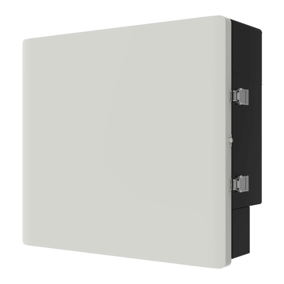
X1-Matebox is a critical part for SolaX all in one energy
storage system, which integrates the AC breaker/switch
unit/CT and so on. It can easily be installed compared to
the traditional separate system. This unit can be used with
SolaX X1-Hybrid G4 and X1-Fit G4 series inverters.
There are 2 wiring diagrams for your system connection
reference, please follow your local policy to choose which
one is suitable for your side.
Diagram A: Neutral line and PE line are separated
from each other, all loads connect to the EPS (Off-
grid) port;
PV1
PV2
Inverter
BAT CT
EPS
Grid
(Off-grid)
Main Breaker
X1-Matebox
E-BAR
Battery
Distribution Box
Loads
N-BAR for loads
2. Overview
509 mm
185 mm
Name
Description
Object
A
EPS (Off-grid)1
EPS (Off-grid)1 output port of the inverter
Grid1 output port of the inverter
B
Grid1
Grid connection port (to local grid)
C
Grid
D
BAT
Battery connection port (to battery pack)
E
CAN
Reserved
F
EPS (Off-grid)2
Reserved
G
Grid2
Reserved
CT connection port of the inverter
H
CT
Load connection port
I
Load
J
BAT(INV)
Battery connection port of the inverter
3. Preparation
3.1 Check Packing List
Open the package and check the materials and accessories according the following list.
Matebox x1
Bracket A x1
BROWN
BROWN
BULE
BULE
Yellow/Green
Yellow/Green
BROWN
BROWN
BULE
BULE
16 mm R-type
AC cable x1
terminal x1
Battery adapter line
EPS cable x1
6 mm BAT terminal x2
positive x1, negative x1
AC waterproof
Flange nut x4
cover x1
3.2 Tools
Diagonal plier
Philips screwdriver
Crimping tool
Hexagon keys
4. Mounting
The bracket of the matebox is composed of three parts.
Bracket A is used to install the matebox. Bracket B is
used to fix the bracket position of the inverter, and
Bracket C is used to fix the bracket position of the
battery.
X1-Matebox advanced
Matebox
Grid
Diagram B: Neutral line and PE line are combined
together, all loads connect to the EPS (Off-grid)
port.
PV1
PV2
Inverter
BAT CT
EPS
Grid
(Off-grid)
Main Breaker
X1-Matebox
L
N
PE
E-BAR
Grid
Battery
Loads
N-BAR for loads
A B C
F G
(Expansion bolt,
European terminal
Gasket, Self-tapping
Bracket B x1
6 mm x6, 16 mm x4
bolt) x2
Bracket C x1
Earthing conductor
(400 mm x1, 250 mm
x2)
WiFi dongle x1
N-terminal adjacent
bridge x1
Key x4
Documents
(for AU market)
Φ10 Drill
Crimping plier
Monkey wrench
External/Inner
hexagonal wrench
Marker pen
Rubber hammer
Inverter bracket
Bracket B
Bracket A
Bracket C
BAT bracket
Step 1: Connect all brackets
First of all, connect inverter bracket, Bracket B, Bracket A, Bracket C and BAT bracket all together with
flange nuts.
Fix the inverter bracket on bracket B;
Then set bracket C on bracket A;
Load
Step 2: Connect the BAT bracket and battery and push the whole structure to the wall
L
N
Grid
Step 3: Fix the position, drill holes and install the whole structure on the wall
a) With the position of the brackets as a template in
step 2, use a spirit level to mark the holes needed
Distribution Box
on the wall with a marker pen.
a)
D
E
c) Insert expansion bolts into the holes, use rubber
hammer to knock the expansion bolts into the wall.
H
I
J
Rubber hammer
c)
Step 4: Install inverter
Make sure all brackets (bracket A, bracket B, bracket C, inverter bracket and BAT bracket) are well and firmly
installed.
a) Take the AC waterproof cover from the matebox
(instead of the one from D version inverter) and
connect the AC cable and EPS cable through the
AC waterproof cover to the inverter. (For details,
please refer to the documents of the inverter.)
c) Use the inner hexagonal wrench to tighten the
inner hexagonal screw on the right side of the
inverter.
Step 5: Install matebox
a) Cut off the strips of the box except the strips on the back of the box before installing the box. Open the
unlocked buckler of the matebox, open the upper cover and remove the protective cover; (open the
button by hand, open the cover and slide upwards.)
a)
b) Put the matebox on the bracket. Make sure the box is well fixed on the bracket by screwing all nuts
tightly.
b)
Inverter bracket
Monkey wrench
Bracket B
Torque: 1.5±0.2 N·m
Bracket A
Bracket C
Monkey wrench
Torque: 1.5±0.2 N·m
BAT bracket
Note: The position of the battery base
mounting screws are two positions on the
inner side, refer to the following figure.
b) Move away the structure and drill holes at marked
spots with depth of 60 mm.
d) The brackets are aligned with the screws, use the
inner hexagonal wrench to screw the tapping
screws until the expansion bolt "bang" is heard.
Expansion bolts
b) Hang the buckle on the inverter to the
corresponding position of the backplane.
a)
Inner hexagonal
wrench
c)
Torque: 1.2±0.1 N·m
Then set bracket B on bracket A and fix it with
screws;
Monkey wrench
Torque: 1.5±0.2 N·m
Then bracket C is fixed on BAT bracket and the
screws are locked.
Monkey wrench
Torque: 1.5±0.2 N·m
Φ10 drill
b)
Screw
External hexagonal wrench
d)
b)
Inverter
Battery
d)
Philips screwdriver
Torque: 1.5±0.2 N·m
Philips screwdriver
Torque: 1.5±0.2 N·m
Advertisement

Related Manuals for SolaX Power X1-Matebox


Summary of Contents for SolaX Power X1-Matebox
- Page 1 1. Introduction Monkey wrench Bracket B Monkey wrench X1-Matebox is a critical part for SolaX all in one energy Torque: 1.5±0.2 N·m Torque: 1.5±0.2 N·m storage system, which integrates the AC breaker/switch Then set bracket C on bracket A;...
- Page 2 6.3 Ground wire connections 5. Monitoring Connection There are three parts that need to be grounded, one is between the inverter and the matebox, one a) Insert the WiFi dongle into the Dongle port of the inverter. between the matebox and the battery and the other between the upper cover and the matebox. b) Take out the antenna from the box of monitoring accessories and install the antenna on bracket A and tighten it by hand.
Need help?
Do you have a question about the X1-Matebox and is the answer not in the manual?
Questions and answers