
Related Manuals for Deye BOS-W


Summary of Contents for Deye BOS-W
- Page 1 Installation and Operation Instructions LITHIUM STORAGE SYSTEM BOS-W Issue:02 Date:20241023...
-
Page 2: Table Of Contents
3. Transport to the end customers ................8 3.1 Provisions on Shipping of Battery Modules .............8 3.2 Storage Position of the battery packaging module ........10 4. Description and installation of BOS-W battery ............10 4.1 Installation Precautions ................. 10 4.2 BOS-W Product Description ................10 4.2.1 Product introduction ................ - Page 3 5.3 Fault viewing interface ...................33 5.4 Maintenance Interface .................. 35 6. BOS-W fault description ..................35 7. Summary of fault types in BOS-W’s screen and HVESS-Monitor ......38 8 Maintenance and upgrade ..................40 8.1 Maintenance of BOS-W ................. 40 8.2 USB’s Upgrade Step ..................41 9.
-
Page 4: Important Information In The Manual
The installation and operation manual applies to the modular battery energy storage system. Please carefully read this installation and operation manual to ensure the safe installation, preliminary debugging, and maintenance of BOS-W. Installation, preliminary debugging, and maintenance must be carried out by qualified and authorized personnel. Please keep this... -
Page 5: Meaning Of Symbols
1.3 Meaning of Symbols This manual contains the following types of warnings: Danger! It may cause an electric shock. Even when the equipment is disconnected from the power grid, the voltage-free state will have a time lag. Danger! If the instructions are not observed, death or severe injury may occur. - Page 6 • Store the battery module in a dry place within the temperature range specified in the data sheet. • Do not open, drill through or drop the battery cell or module. • Do not expose the battery cell or module to high temperatures. •...
-
Page 7: General Safety Information
Danger! Failure to comply with the safety information can lead to life-threatening situations. 1. Improper use can cause death. Operators of BOS-W must read this manual and observe all safety information. 2. Operators of BOS-W must comply with the specifications in this manual. -
Page 8: Installation Environment
• The battery energy storage system can only be installed and operated in an enclosed space. The working environment temperature range of BOS-W is -20℃~ 55℃, and the maximum humidity is 85%. The battery module shall not be exposed to the sun or placed directly beside the heat source. -
Page 9: Quality Certificate
1.8 Requirements for Installation Personnel All work shall comply with local applicable regulations and standards. The installation of BOS-W can only be completed by electricians with the following qualifications: • Trained in dealing with hazards and risks associated with the installation and operation of electrical equipment, systems, and batteries. -
Page 10: Safety
2. Safety 2.1 Safety rules To avoid Property damage and personal injury, the following rules shall be followed when working on the hazardous live parts of the battery energy storage system: • It is available for use. • Ensure that it will not restart. •... -
Page 11: Transport To The End Customers
A tilting of the battery rack may cause injury. The maximum weight of a single battery rack of BOS-W can reach 368 kg. When tilted, they may overturn, causing injury and damage. Ensure that the battery cabinet is on a stable surface and that it does not tilt due to load or force. - Page 12 The battery energy storage system can be damaged, if not Properly transported. The battery module can only be transported vertically. Note that these parts may be top-heavy. Failure to follow this instruction may result in damage to the part. During transportation, the battery storage rack may be damaged when it is installed with the battery module.
-
Page 13: Storage Position Of The Battery Packaging Module
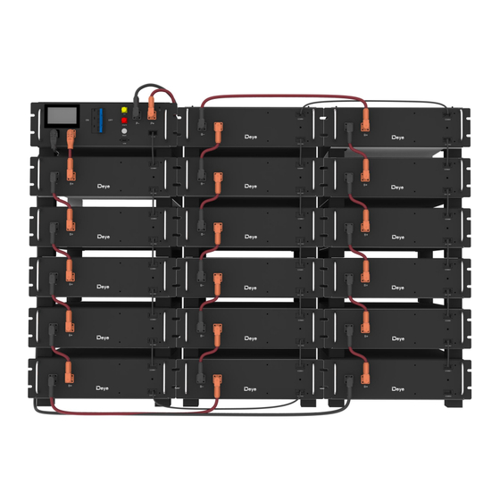
4.2 BOS-W Product Description 4.2.1 Product introduction BOS-W is a high-voltage lithium-ion battery system. It Provides a reliable backup power supply for supermarkets, banks, schools, farms and small factories to smooth the load curve and achieve peak load transfer. It can also improve the stability of renewable systems and promote the... - Page 14 It is characterized by high integration, good reliability, long service life, wide working temperature range, etc. The battery energy storage system is modular. Each battery module has a capacity of 5.12 kWh. It can support up to 17 battery modules in series. Its total energy can be expanded from 25.6 kWh to 87.04 kWh.
-
Page 15: Product Selection
4.2.2 Product selection 1.Varying in the quantity of your products can meet various application demands. Usually customers are allowed to make choices within 5~17. 2. Our products usually work in a stacking way. The number of battery module in one cluster shouldn’t exceed 7 (not including high-voltage box). -
Page 16: Technical Data
4.3 Technical Data Cell Chemistry LiFePO Module Energy(kWh) 5.12 Module Nominal Voltage(V) 51.2 Module Capacity (Ah) Battery Module Number BOS- BOS-W40 BOS-W60 BOS-W85 Battery Module Qty in Series 5 (Min) 17 (Max) (Optional) System Nominal Voltage(V) 409.6 614.4 870.4 System Operating Voltage(V) 220~292 352~467.2 528~700.8... -
Page 17: Preparation
4.4 Preparation 4.4.1 Tools required TOOL With M4*8 countersunk head screws, lock the Phillips screwdriver screws on the side of the support to secure the overall support. Use M6*20 hexagon assembly and flange nut to Sleeve secure the ground cable between the bag and the bag. -
Page 18: Description Of High-Voltage Control Box
4.6 Description of High-Voltage Control Box Name Description Position Connection position of the common negative pole ① Front of the battery (black). Connection position of the common positive pole of ② Front the battery (orange). Used to manually control the connection between ③... - Page 19 Connection position of PCS positive pole (orange). Front Grounding wire Connection to the battery rack and the ground ⑫ Front identification point. Connection position with next BOS-W-PDU-2 ⑬ OUT COM Rear communication input. Connection position with previous BOS-W-PDU-2 ⑭ IN COM Rear communication output.
-
Page 20: Description Of Battery Module In Racks
4.7 Description of Battery Module in Rack... - Page 21 Description Quantity ① High-voltage control box 1000V/100A ② 5.12kWh battery module (general) ③ Standard 120Ω terminal resistor Communication cable (160 mm for battery module, ④ 250 mm for high-voltage control box) CAT5E FTP Standard 26AWG black 140 mm positive power cord of high-voltage control ⑤...
- Page 22 ⑯ M6 Hexagon nut Standard ⑰ Screw Standard Per high-voltage box include: Standard connecting Ground wire A (ground wire B for external connection cable A (connecting of battery rack is not provided) UL 1015 10AWG yellow ⑧ the high-voltage green control box) ⑩...
- Page 23 Definition Definition of PCS Racks in Racks in of the communication parallel IN parallel OUT COMM1 interface interface BMS_CAN BMS_CAN 485B- BMS_CAN BMS_CAN 485A+ DO2+ PCANH PCANL 485A+ 485B- Defines the external interface of a battery pack Definition of the battery module interface Comm1 Comm2 INT_CANH...
-
Page 24: Installation Of The Battery Module
4.8 Installation of the Battery Module Insufficient or no grounding may cause an electric shock. Device malfunctions, and insufficient or no grounding may cause device damage and life-threatening electric shocks. Note: Before installing the battery, please turn the manual switch of the high-voltage control box to the off position. -
Page 27: Wiring Instructions
Instructions 4.10 Wiring 4.10.1 contents Package 1: Socket Package 2: Grommet 3: Gripping Jaw 4:Nut 4.10.2 Plug Instruction Assembly Step1:Strip off the jacket of the cable. Step2:Put the nut, the Grommet and the gripping jaw on the cable as shown. Step3:Insert the conductor into the lug. - Page 28 Step4 : Crimping the lug as shown (A 1~2mm horn is left out of the tail cable to prevent crushing the conductor). Table Electric The length Plug riveting Suggested Compression Cable Cable current of the tool width B crimp height ratio square outside...
- Page 29 After install the socket, we can mate directly, you don’t need press the button. It is install over when you hear a sound. (Pre-pull the socket up, unable to come out, to ensure that the assemble is in place.) ② Before you pull out the plug, please turn off the power first. ③...
-
Page 30: Battery Cluster Connected To Inverter
4.11 Battery cluster connected to inverter For the Australian Market, an over-current Protection and isolation device that isolates both positive and negative conductors simultaneously is required between the battery system and inverter Battery cluster connected to inverter Notice: The length of the communication line between the inverter and the battery should not exceed 30m. - Page 31 Two battery clusters connected to the inverter Three battery clusters connected to the inverter...
-
Page 32: System Startup And Shutdown
Multiple battery packs are connected to the inverter The number of battery packs in each cluster must be the same in each group, and the number of battery packs in group A and Group B can be different. 4.12 System startup and shutdown Startup Procedure After connecting the battery cables, press the air switch button on the high-voltage control box to turn OFF to ON. -
Page 33: Procedure For Configuring Battery Packs
Turn off the circuit breaker after the battery pack is closed. 4.13 Procedure for configuring battery packs Steps: After connecting the battery cables, press the air swim key to enter the main interface of system maintenance. The operation shall be performed by a Professional. Tch button on the high-voltage control box to turn OFF to ON. - Page 34 Click the icon on screen to enter the maintenance system password confirmation interface. Enter the password 123 and press the Confirm Click “BMU Number” in the lower left corner, enter the number of packs in system and click “OK” to finish configuring the number of packs. After the setting is successful, you need to restart.
-
Page 35: External 12V Power Supply Of High-Voltage Control Box
4.14 External 12V Power Supply of High-Voltage Control Box To operate the high-voltage control box with an external 12V power supply, please contact our service personnel. Hotline: +86 0574 8612 0560, Email: service-ess@deye.com.cn . In the factory configuration, the high-voltage control box is supplied with working voltage from an internal power supply unit. -
Page 36: Description Of User Interface
5.2 Description of User Interface (1) Basic Parameters Click this icon to enter the system maintenance System maintenance interface. icon Total battery voltage Voltage Battery current, the positive value representing Current discharge, the negative value representing charge Battery remaining energy Accumulated discharging energy Total energy (2) Fault Indication:... - Page 37 Enter the password 123 and press the Confirm key. The enter main interface of system. The operation shall be performed by a Professional. Fault warning OV turns red: expression overvoltage, click OV to view the detail fault. UV turns red: expression undervoltage, click UV to view the detail fault. OT turns red: expression overtemperature, click OT to view the detail fault.
-
Page 38: Maintenance Interface
For safety, please unplug the power cord of the positive and negative interfaces before maintenance. Note: When inserting the SD card, unplug the battery power cord and manually turn the air switch to the off position. 6. BOS-W fault description Different types of faults are below: Fault types Trigger conditions... - Page 39 overtemperature alarm (>50℃, 2s) Discharge Exceeding the parameter set value and set time overtemperature (>55℃, 2s) Protection Exceeding the parameter set value and set time Charge under temperature alarm (<5℃, 2s) Exceeding the parameter set value and set time Charge under temperature Protection (<0℃, 2s) Exceeding the parameter set value and set time (<-...
- Page 40 BMU connector Exceeding the parameter set value and set time overtemperature alarm BMU connector overtemperature Exceeding the parameter set value and set time Protection Power loop Exceeding the parameter set value and set time overtemperature alarm Power loop overtemperature Exceeding the parameter set value and set time Protection SOC too low Exceeding the parameter set value and set time...
-
Page 41: Summary Of Fault Types In Bos-W's Screen And Hvess-Monitor
BMUs are the system abnormal Note: For more information, please contact us. Email: service- ess@deye.com.cn, Service Hotline: +86 0574 8612 0560. 7. Summary of fault types in BOS-W’s screen and HVESS-Monitor Screen Protection event HVESS-Monitor Protection HVESS-Monitor alarm event Abbreviation... - Page 42 voltage level-2 alarm Protection alarm Excessive differential Excessive differential Excessive differential temperature level-2 alarm temperature Protection temperature alarm Total charge voltage too Total voltage too high Total voltage too high alarm high Protection Cell overvoltage level 2 Cell overvoltage Protection Cell overvoltage alarm alarm Charge voltage too low...
-
Page 43: Maintenance And Upgrade
Before maintenance, ensure that BOS-W is decommissioned according to relevant Provisions. Note: All maintenance work shall comply with local applicable regulations and standards. The USB disk port of BOS-W has the functions of upgrading firmware and recording battery data, which can be used as an auxiliary tool. -
Page 44: Usb's Upgrade Step
• Using the monitoring software, check whether the SoC, SOH, battery voltage and temperature of the battery module are abnormal. • Shut down and restart BOS-W once a year. Note: If the system is installed in a polluted environment, maintenance and cleaning must be carried out at short intervals. -
Page 45: Battery Module Storage
10. Disposal For details related to the disposal of battery modules, please contact us. Service Hotline: +86 0574 8612 0560, Email: service-ess@deye.com.cn. For more information, please visit http://deyeess.com. Observe applicable regulations on waste battery disposal. Immediately stop the use of damaged batteries. -
Page 46: Legal Notice
Deye ESS Technology Co., Ltd Made in China Legal Statement The information contained in the document is the Property of Deye ESS Technology Co., Ltd. D All information shall not be published in whole or in part without the written permission of Deye.
Need help?
Do you have a question about the BOS-W and is the answer not in the manual?
Questions and answers