Table of Contents
Advertisement
Quick Links
Advertisement
Table of Contents

Related Manuals for Deye BOS A Series


Summary of Contents for Deye BOS A Series
- Page 1 Installation and Operation Instructions LITHIUM STORAGE SYSTEM BOS-A Version:V1.1...
-
Page 2: Table Of Contents
CONTENT 1.Important information in the manual .................1 1.1 Scope ........................1 1.2 Description of BOS-A ..................1 1.3 Meaning of Symbols ..................2 1.4 General Safety Information ................4 1.5 Disclaimer ......................4 1.6 Installation environment ..................5 1.7 Quality Certificate .................... 6 1.8 Requirements for Installation Personnel ............6 2. - Page 3 4.4.2 Auxiliary Tools and Materials Required ..........20 4.4 Description of Rack ..................21 4.4.1 11-layer battery cluster rack Parts description ........21 4.4.2 Installation of Rack ................22 4.5 Description of Battery Module ..............23 4.7 Description of High-Voltage Control Box ............24 4.8 Description of Battery Module in Rack ............25 4.9 Right wiring method ..................
-
Page 4: Important Information In The Manual
Please observe the applicable local laws, regulations, and standards. Standards and legal provisions of other countries may be inconsistent with the provisions and specifications in this manual. In this case, please contact our after-sales service personnel, hotline: +86 0574 8612 0560, email: service-ess@deye.com.cn. 1.2 Description of BOS-A Model... -
Page 5: Meaning Of Symbols
1.3 Meaning of Symbols This manual contains the following types of warnings: Danger! It may cause an electric shock. Even when the equipment is disconnected from the power grid, the voltage-free state will have a time lag. Danger! If the instructions are not observed, death or severe injury may occur. - Page 6 • Store the battery module in a dry place within the temperature range specified in the data sheet. • Do not open, drill through or drop the battery cell or module. • Do not expose the battery cell or module to high temperatures. •...
-
Page 7: General Safety Information
If there are any questions, please contact Deye after service. 1.5 Disclaimer DEYE ESS TECHNOLOGY CO., LTD shall not be liable for personal injury, property loss, product damage and subsequent losses under the following circumstances. • Failure to comply with the provisions of this manual. -
Page 8: Installation Environment
• Incorrect use of this product. • Unauthorized or unqualified personnel repair the product, disassembly the rack and perform other operations. • Use of unapproved spare parts. • Unauthorized modifications or technical changes to the product. 1.6 Installation environment • The battery energy storage system can only be installed and operated in an enclosed space. The working environment temperature range of BOS-A is -20℃~ 55℃, and the maximum humidity is 85%. -
Page 9: Quality Certificate
• Mobile use on land or in the air (use on water only with the manufacturer's consent and with the manufacturer's written consent). • Used in medical devices. • Used as a UPS system. Minimum product installation distance The minimum distance to the surrounding building when the battery is installed is 100mm, and the minimum distance between the two products is 100mm. - Page 10 • Trained on installation and debugging of electrical equipment. • Understanding and complying with the technical connection conditions, standards, guidelines, regulations, and laws applicable. • Knowledge of handling lithium-ion batteries (transportation, storage, disposal, hazard source). • Understanding and complying with this document and other applicable documents.
-
Page 11: Safety
2. Safety 2.1 Safety rules To avoid property damage and personal injury, the following rules shall be followed when working on the hazardous live parts of the battery energy storage system: • It is available for use. • Ensure that it will not restart. •... - Page 12 Warning! Improper use can cause damage to the battery cell. • Do not expose the battery module to rain or soak it in liquid. • Do not expose the battery module to a corrosive environment (such as ammonia and salt). •...
-
Page 13: Transport To The End Customers
3. Transport to the end customers 3.1 Provisions on Shipping of Battery Modules: It is necessary to comply with the relevant regulations and provisions on roads for shipping lithium-ion products in the corresponding countries. It is prohibited to smoke in the vehicle during transportation or in the vicinity during loading and unloading. - Page 14 If possible, do not remove the transport packaging before arrival at the installation site. Before removing the transport protector, check if the transport packaging is damaged, and check the impact indicator on the outer packaging of the battery converter. If the impact indicator is triggered, the possibility of transport damage cannot be ruled out.
-
Page 15: Storage Position Of The Battery Packaging Module
3.2 Storage Position of the battery packaging module The battery module can only be transported in an upright position. Please note that the battery rack may be very top-heavy. -
Page 16: Description And Installation Of Bos-A Battery
4. Description and installation of BOS-A battery 4.1 Installation Precautions WARNING! Possible damage to the building due to static overload 1. The total weight of the battery storage system is 1586kg. Ensure that the installation site has sufficient bearing capacity. 2. -
Page 18: Product Selection
4.2.2 Product selection We offer our customers three options: The first option: requires 7 to 10 battery modules can choose a 11-layer product solution. The product appearance is shown in the following figure:... - Page 19 The second option: need 11~13 battery modules can choose 14-layer product solution. The product appearance is shown in the following figure:...
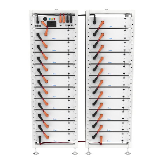
- Page 20 The third option: need 14~21 battery modules can choose two 11-layer product solution. The product appearance is shown in the following figure:...
-
Page 21: Technical Data
4.3 Technical Data 7 battery modules 53.76 kWh 8 battery modules 61.44 kWh 9 battery modules 69.12 kWh 10 battery modules 76.8 kWh 11 battery modules 84.48 kWh 12 battery modules 92.16 kWh 13 battery modules 99.84 kWh The energy of the battery system 14 battery modules 107.52 kWh (7~21 battery modules) - Page 22 Module capacity 200Ah 7 battery modules 235.2~306.6V Working voltage 13 battery modules 436.8~569.4V 21 battery modules 705.6~919.8V Working temperature Charge: 0~55℃/Discharge:-20~55℃ Humidity 5% - 85% (RH) The altitude of the installation site ≤ 3000 m 11-layer: 1900×610×610mm Dimensions (H x W x D) 14-layer: 2350×610×610mm Two 11-layer: 1900×1320×610mm Warranty period...
-
Page 23: Preparation
4.4 Preparation 4.4.1 Tools required TOOL •Refer to installation instructions for 11-layer PHILIP2# hex wrench battery cluster rack 10mm hexagon socket • Fix the expansion screw 24mm wrench • Adjust the height of the base and tighten the nut. 4.4.2 Auxiliary Tools and Materials Required AID/MATERIAL Auxiliary tools/materials 1. -
Page 24: Description Of Rack
4.4 Description of Rack 4.4.1 11-layer battery cluster rack Parts description Description ① Heat insulation foam ② Crossbeam ③ Big tripod ④ Small tripod ⑤ L-bracket assembly ⑥ Rack fastener ⑦ Bottom plate parts ⑧ Base ⑨ Diagonal brace... -
Page 25: Installation Of Rack
4.4.2 Installation of Rack Take out two side beams and upper and lower crossbeams to form a rectangular frame, connect with side beams and crossbeams using big tripods and small tripods, and then fix big and small triangular supports with side beams and crossbeams using M6*12 outer hexagon cross combination screws and a PHILIP2 # screwdriver. -
Page 26: Description Of Battery Module
4.5 Description of Battery Module Name Description ① Battery module negative pole (black) ② COMM2 Connection position of battery module communication and power supply output ③ Battery module positive pole (orange) ④ COMM1 Connection position of battery module communication and power supply input... -
Page 27: Description Of High-Voltage Control Box
4.7 Description of High-Voltage Control Box No. Name Description ① Ethernet Features not yet developed PCS COM battery communication terminal: (RJ45 port) follow the CAN protocol (default baud rate: 500bps) and RS485 ② PCS COM protocol (default baud rate:9.6bps), used to output battery information to the inverter. -
Page 28: Description Of Battery Module In Rack
A start switch of 12VDC power inside the high-voltage control ⑬ START ⑭ HV light indicator High-voltage hazard indicator (yellow) ⑮ ALRM light indicator Battery system fault alarm indicator (red)Y ⑯ PCS1- First PCS negative connection position (black) ⑰ PCS2- Second PCS negative connection position (black) ⑱... - Page 29 Description quantity 1000V/160A ① Standard High-voltage control box ② 7.68kWh battery module (general) Standard ③ 120ohm terminal resistor Standard Communication cable (110 mm for battery module, ④ 200 mm for high-voltage control box) CAT5E FTP Standard 24AWG black 180 mm positive power cord of high-voltage control ⑤...
- Page 30 Definition of external interfaces on the front panel of the high voltage box Definition of PCS communication Racks in parallel IN Racks in parallel OUT Definition of power interface BMS_CANL BMS_CANL BMS_CANH BMS_CANH YL_ZLA PCANH YL_ZLB PCANL Defines the external interface of a battery pack Definition of the battery module interface Comm1 Comm2...
-
Page 31: Right Wiring Method
4.9 Right wiring method Connect cables correctly according to the figure. Two 11-layer:... - Page 32 11-layer and 14-layer:...
-
Page 33: Installation Of The Battery Module To The Rack
4.10 Installation of the Battery Module to the Rack Insufficient or no grounding may cause an electric shock. Device malfunctions, and insufficient or no grounding may cause device damage and life-threatening electric shocks. Note: Before installing the battery, please turn the manual switch of the high-voltage control box to the off position. -
Page 34: Cable Connection
For the correct installation method shown in the first picture, stack battery packs from bottom to top, and place the high pressure box on the top of the cluster rack. Insert the slide of the cabinet at the top of the rack into the high-voltage control box. After the battery module and control box is inserted into the rack, use M6*20 hex socket combination screws to fix all the lugs of the battery module and control box on the side beam in turn. -
Page 35: Battery Installation Cable Description
4.10.2 Battery installation cable Description For details on how to connect all cables, see Section 4.8. When connecting cables, observe the installation diagram and pay attention to the direction of the communication cables. Otherwise, the products may not work properly due to incorrect cable installation. -
Page 37: Battery Cluster Connected To Inverter
After the battery module is placed in the control box, take out a 200 mm communication cable to connect the communication port of the battery module and the high-voltage control box, and 11x160mm communication cables to connect the battery module communication port (IN-OUT) from top to bottom. - Page 38 Single battery cluster connected to inverter...
- Page 39 Two battery clusters connected to the inverter...
- Page 40 Three battery clusters connected to the inverter...
- Page 41 Multiple battery packs are connected to the inverter The number of battery packs in each cluster must be the same in each group, and the number of battery packs in group A and Group B can be different.When the power current of a single cluster battery exceeds 100A, two P+ and P- channels must be connected.
-
Page 42: System Startup And Shutdown
4.12 System startup and shutdown Startup procedure After connecting the battery cables, press the air switch button on the high-voltage control box to turn OFF to ON. Press the start button and wait for the screen to light up. Complete boot Shutdown procedure Press the start button again and wait for the screen to go off. -
Page 43: External 12V Power Supply Of High-Voltage Control Box
4.14 External 12V Power Supply of High-Voltage Control Box To operate the high-voltage control box with an external 12V power supply, please contact our service personnel. Hotline: +86 0574 8612 0560, Email: service-ess@deye.com.cn . In the factory configuration, the high-voltage control box is supplied with working voltage from an internal power supply unit. -
Page 44: Bos-A' Fault Description
5. BOS-A’ fault description Different types of faults are below: Fault types Trigger conditions Charge over-current alarm Charge over-current Exceeding the parameter set value and set time protection (More than 105A, 2s; more than 125A, 5s; more than Discharge 140A, 2s; lower than 5℃, over-current alarm set value*0.5) Discharge... - Page 45 Excessive differential Exceeding the parameter set value and set time temperature alarm (>10℃, 2s) Excessive differential Exceeding the parameter set value and set time temperature (>15℃, 2s) protection Cell overvoltage alarm To maintain consistency, cut off the charging Cell overvoltage immediately when the full charge calibration rated protection voltage of 3.6V is reached.
- Page 46 alarm Power loop overtemperature Exceeding the parameter set value and set time protection SOC too low Exceeding the parameter set value and set time Total voltage too high Exceeding the parameter set value and set time alarm Total voltage too high Exceeding the parameter set value and set time protection Total voltage too low...
- Page 47 SCHG total voltage acquisition fault Cell voltage The cell voltage acquired is 0 acquisition fault Temperature The temperature acquired is -40℃ acquisition failure Current acquisition fault Current module fault Abnormal Hall current/reference voltage EEPROM storage EEPROM write failure during self-test failure The external RTC failed to enable the charging RTC clock fault...
-
Page 48: Bos-A Screen Displays The Logic
6.BOS-A screen displays the logic 1. After startup, the screen is on for 20 seconds and then off. Each time the touch screen is lit behind the scenes for 20 seconds, and then turned off until the next touch. 2. The first 2s of boot, the screen shows all. 3. - Page 49 ALARM_ID_INSULATION_FAILUR F017 Insulation fault E_TWO ALARM_ID_HEAT_OVER_TEMP_ F018 The heating film is too high LEV_2 F019 ALARM_ID_SOC_LOW_LEV_2 The SOC is too low ALARM_ID_DSG_RELAY_ADHESI F020 The total voltage is too low ALARM_ID_POS_RELAY_ADHESI F021 Total positive relay bonding ALARM_ID_CHG_RELAY_ADHESI F022 The charging relay is glued ALARM_ID_HEAT_RELAY_ADHES F023 The heating relay is glued...
- Page 50 F056 ALARM_ID_LC_COMM_LOST LC communication loss ALARM_ID_PACK_AFE_COMM_E F057 BMU AFE communication fails RROR, F058 ALARM_ID_BLE_INIT_FAULT Description Bluetooth initialization failed ALARM_ID_CELL_TYPE_MISMAT F059 The battery type does not match CH_ERROR Note: more information, please contact Email: service-ess@deye.com.cn, Service Hotline: +86 0574 8612 0560.
-
Page 51: Maintenance And Upgrade
7. Maintenance and upgrade Warning! Improper decommissioning may cause damage to the equipment and/or battery inverter. Before maintenance, ensure that BOS-A is decommissioned according to relevant provisions. Note: All maintenance work shall comply with local applicable regulations and standards. The USB disk port of BOS-A has the functions of upgrading firmware and recording battery data, which can be used as an auxiliary tool. -
Page 52: Usb's Upgrade Step
7.2 USB’s Upgrade Step USB type: USB2.0, FAT32. Create the upgrade folder according to the directory. Place the upgrade file provided by the supplier in the upgrade folder. Turn on the battery, and insert the USB flash disk after the blue indicator is on. After the blue light indicator flashes and turns off, pull out the USB flash disk to complete the upgrade. -
Page 53: Battery Module Storage
8. Battery Module Storage To ensure the battery service life, the storage temperature shall be kept between 0°C~35°C. The battery shall be cycled at least once every 6 months. To minimize self-discharge in a long storage period, disconnect the battery connection (1/2) of the high-voltage control box of the DC connecting cable. -
Page 54: Disposal
9. Disposal For details related to the disposal of battery modules, please contact us. Service Hotline: +86 0574 8612 0560, Email: service-ess@deye.com.cn. For more information, please visit http://deyeess.com. Observe applicable regulations on waste battery disposal. Immediately stop the use of damaged batteries. -
Page 55: Legal Notice
China Legal Statement The information contained in the document is the property of Deye ESS Technology Co., Ltd. D All information shall not be published in whole or in part without the written permission of Deye ESS Technology Co., Lt.
Need help?
Do you have a question about the BOS A Series and is the answer not in the manual?
Questions and answers