
Related Manuals for Deye GE-FL60


Summary of Contents for Deye GE-FL60
- Page 1 Installation and Operation Installations High Voltage Battery GE-FL60 Version: V1.1...
-
Page 2: Table Of Contents
Table of contents All Rights Reserved ....................3 About This Manual ....................3 1 Safety Precautions ....................4 1.1 Personal Requirements ................... 4 1.2 Electrical Safety ....................5 1.3 Battery Safety ....................6 1.4 Hoisting and Transportation ................6 1.5 Installation and Wiring ..................6 1.6 Operation and Maintenance ................ - Page 3 5.4 Cable connection ................... 36 5.4.1 Cable connections inside BESS ................36 5.4.2 Auxiliary power supply ................... 39 5.4.3 Cable connection between BESS ................34 5.4.4 Cable connection between the inverter and BESS ..........35 5.5 Operation after cable connection ..............35 5.6 Battery Connection ..................
-
Page 4: All Rights Reserved
Software Licenses • It is prohibited to use data contained in firmware or software developed by Deye ESS, in part or in full, for commercial purposes by any means. • It is prohibited to perform reverse engineering, cracking, or any other operations that compromise the original program design of the software developed by Deye ESS. -
Page 5: Safety Precautions
Danger! Failure to follow the instructions bearing this sign may result in a serious accident resulting in death or serious injury. Warning! Failure to follow the instructions of this sign may result in a serious accident resulting in serious personal injury. Caution! Failure to follow the instructions of this sign may result in minor or moderate injury. -
Page 6: Electrical Safety
1.2 Electrical Safety Danger! • Touching the power grid or the contact points and terminals in the devices connected to the power grid may lead to electric shock! All circuit connectors must be disconnected during maintenance. • The battery side or the power grid side may generate voltage. Always use a standard voltmeter to ensure that there is no voltage before touching. -
Page 7: Battery Safety
• Do not store batteries with inflammable and explosive materials. This may cause product damage or property loss. Maintain the battery according to this manual. Deye ESS is not responsible for insurance and claims if maintenance is not performed in accordance with this manual. -
Page 8: Operation And Maintenance
GE-FL60 lithium iron phosphate battery the new energy storage products developed and produced by DEYE ESS, which can be used to support the reliable power supply of various equipment and systems. The GE-FL60 is particularly suitable for high-rate cyclic charging and discharging scenarios. -
Page 9: External Design
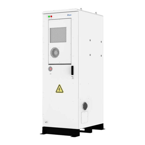
2.2 External Design Cabinet Appearance ① Indicator light: When the green light ⑥ Door switch: Insert the key to open the ESS. comes on, the BESS is Run. When the red light comes on, the BESS gives an alarm. ② Air conditioning outlet: Hot air in the air ⑦... -
Page 10: Air-Conditioner Design
2.3 Air-conditioner Design System built-in air conditioner cooling The air conditioning system uses air cooled air conditioner, keep the BESS at a constant temperature. Energy storage Air Conditioning Model DY-CNA20-BP(US) Rated Voltage AC 240V Rated Frequency 60Hz Rated Cooling Capacity 2100W Rated Cooling Current 4.15A... -
Page 11: Internal Design
2.4 Internal Design 2.4.1 Internal Equipment ①Air conditioner Cooling the BESS. ②Travel switch Check whether the BESS system door is closed. A device used to detect smoke in a fire and sound ③Smoke detector an alarm when smoke is detected. A device used to measure temperature and ④Heat detector sound an alarm if it detects excessive... - Page 12 When combustible gas is detected, the ①Air outlet outlet will automatically pop out and need to be manually reset after use. Detect combustible gases and notify ②Combustible gas sensor aerosol fire suppression systems ③Serial relay Control system ④Terminal line For connecting cables ⑤Switching Mode Power Supply Power source ⑥Terminal line...
-
Page 13: Battery Introduction
2.4.2 Battery Introduction Battery Module Battery Type LiFePO4(LFP) Nominal Voltage 51.2Vdc Rated Capacity 100Ah Rated Energy 5.12kWh Nominal Charge/Discharge Current 100A Peak. Discharge Current 125A Charge Temperature 0~55°C Discharge Temperature -20℃~55°C Storage Temperature 0℃~35°C Ingress Protection IP20 Dimension (W/D/H) 440*570*133mm Weight Approximate 45kg... - Page 14 Detection of aerosol concentrations in the ①Aerosol sensor Provides electrical energy storage and ②Battery module output ③CCS Cells Contact System ④Vent hole Heat dissipation ⑤Battery Negative- ⑥Battery Positive+ ⑦Fan Promote internal and external air flow ⑧BMU Battery monitoring Power Distribution Unit Operating Voltage 120~750Vdc Nominal Charge/Discharge Current...
- Page 15 Connection position of the common negative pole of the ①B- battery ②B+ Connection position of the common positive pole of the battery Used to manually control the connection between the battery ③DC switch rack and external devices ④ALRM light indicator Battery system fault alarm indicator ⑤HV light indicator High-voltage hazard indicator...
-
Page 16: Indicator Light Design
2.4.3 Indicator light Design Indicator light: When the green light comes on, the BESS is Run. When the red light comes on, the BESS gives an alarm. 1. The following faults trigger either level 2 fault. The cabinet ALARM red light is on, the external ALARM light is on, and the RUN indicator is off. - Page 17 too large fault Temperature difference too large BMU repeat fault 41 BMU communication fault fault High SOC fault BMU repeat fault 42 BMU number anomaly Cell temperature low Internal CAN Abnormal Mot total voltage fault communication fails pressure collection Abnormal Temperature Pre-charge resistance PCS CAN collection of the BMS...
- Page 18 Indicator: Steady yellow indicates that PDU is working properly and the battery power circuit is closed. When the red light is on, PDU gives an alarm. The following faults trigger any level 2 fault, the battery ALARM red light is on, the PDU ALARM light is on, and the HV indicator is off.
-
Page 19: Transport And Storage
fault pressure collection 49 Current acquisition fault 3 Transport and storage 3.1 Transportation 1 Preventive Measures Failure to ship and store products in accordance with the requirements of this manual may void the warranty. 2 Mode of Transportation It can be transported by cars, trains and ships. 3.2 Transportation Requirement The following conditions should be met for the transportation of BESS: ... -
Page 20: Storage Requirement
Class 9 Miscellaneous Dangerous Goods and UN Identification Label 3.3 Storage requirement • During the rainy season to prevent possible condensation or its bottom being soaked by rain. • BESS should be stored on higher ground. Raise container bases based on site conditions. The specific height should be reasonably determined according to the geological and meteorological conditions of the site. -
Page 21: Mechanical Installation
4 Mechanical Installation 4.1 Inspection Before Installation 4.1.1 Open the package i. Find a claw hammer(or flat head screwdriver) to pry open the nail (refer to the following picture to operate). - Page 22 ii. Pry it open and hammer it flat. iii. First, pry out all the nails, then disassemble the top plate, and disassemble the surrounding plate. iv. Unscrew the two forklift protection plates at the bottom of the cabinet.
- Page 23 v. Unscrew the front and back four fixing screws, you can use the forklift truck transport.
-
Page 24: Deliverables Inspection
4.1.1 Deliverables Inspection Check whether deliverables are complete against the packing list. 4.1.2 Product Inspection Check BESS and internal equipment for damage. If you find any problems or have any questions, please contact the agency or Deye ESS. -
Page 25: Installation Environment
4.2 Installation Environment • The environment around the installation site should be dry and well-ventilated. • The installation site should be far away from the concentration of toxic and harmful gases, and away from flammable, explosive and corrosive materials. • The installation site should be far away from residential areas to avoid noise. Installation site requirements Unreasonably constructed foundation will bring great troubles to the installation of the BESS, affecting the normal opening and closing of the doors and the normal operation. -
Page 26: Installation Spacing Requirement
Foundation laying drawing(Unit: mm) Notice! : The dregs excavated during the foundation construction should be removed immediately to avoid affecting the hoisting in the later stage. 4.3 Installation Spacing Requirement Installation spacing drawing 1(Unit: mm)... - Page 27 Both sides of the inverter can be installed. But only needs to be installed on one side. Notice! : If you want to install an inverter, reserve 700mm on the inverter installation side. Installation spacing drawing 2(Unit: mm) Serial number Distance...
-
Page 28: Installation Of Inverters And Bess
4.4 Installation of inverters and BESS First remove the M12 screws on the BESS with the wrench of the M12 and install the inverter rack on the BESS. Second fix the inverter on the rack, and drive three screws on each side with a phillips screwdriver to complete the installation. -
Page 29: Transportation And Lifting
4.5 Transportation and lifting 4.5.1 Transportation Forklift Transport If the installation site is flat, use a forklift to move the equipment. The bottom of the machine has a special forklift transport fork hole. A forklift with a rated load of more than 1500kg should be used. - Page 30 Wooden case should be placed face up ① Fragile ② Product should be stored against moisture ③ Prohibit to turn over product packaging during operation ④ Prohibit to stack ⑤ Center of gravity location ⑥ Forklift safety precautions ⑦ Product information ⑧...
-
Page 31: Hoisting Equipment
If a forklift is used, the following requirements must be met: The forklift should be equipped with sufficient load capacity. The foot length of a forklift truck should meet the equipment requirements. Caution! : Heavy unbalanced load when lifted REFER TO MARKINGS FOR CENTER OF GRAVITY LOCATION Notice! 1. -
Page 32: Hoisting
• A professional instructor is needed in the whole hoisting process. • The strength of the sling used should be able to withstand the weight of the devices. • Ensure that all sling connections are safe and reliable, and that the lengths of the slings connected to the corner fittings are equal. -
Page 33: Fixing Methods
4.6 Fixing Methods Fixed by L-angle steel The following figure shows the positions for fixing the cabinet bottom using L-shaped Angle steel. -
Page 34: Electrical Connection
Fix the L-shaped Angle steel to the cabinet first, and then drive the expansion screws to fix the ground. Use screws (M10*30) with torque (30N·m) above and use expansion screw(M12*80) to fix the bolt angle. Due to the uncertainty of drilling accuracy and bit material, it is recommended to choose a drill bit from φ16.5 to φ17. -
Page 35: Preparation Before Connection
Only qualified electrical engineers can carry out work related to electrical connections. Please comply with the requirements in "1 Safety Precautions" of this manual. The Company shall not be liable for any injury or loss of life or property caused by ignoring these safety instructions. 5.2 Preparation before connection Installation preparation tool Item... -
Page 36: Cable Connection
3. Insert the door key and turn it clockwise to eject the handle 4. Turn the handle clockwise to the position shown in the picture to open the front door. Caution! : Please take care to lift this part when closing the door. 5.4 Cable connection Notice! : infrequently used terminal please cover with dust cover protection. - Page 37 Danger! Wrong connection mode: Please do not connect as follows!
-
Page 39: Auxiliary Power Supply
5.4.2 Auxiliary power supply Ground wire requirements>12AWG Live wire and Neutral wire requirements 1 BESS≥12AWG 2 BESSs≥10AWG 3 BESSs≥8AWG 4 BESSs≥7AWG 5 BESSs≥6AWG 6 BESSs≥5AWG Lighting protection communication use Connected to external device communication cable (ECOM Cable 5.0) - Page 40 Auxiliary distribution diagram...
- Page 41 Auxiliary power supply diagram...
-
Page 42: Cable Connection Between Bess
It is recommended that each BESS be connected to power distribution separately. If the power distribution is not connected separately, follow the method recommended by Deye ESS. (Note: Other cables are also connected, which is not shown in the drawing) -
Page 43: Cable Connection Between The Inverter And Bess
5.4.4 Cable connection between the inverter and BESS Open the cabinet door and connect according to the following figure. The negative copper bar is connected to the PDU P- and the negative electrode of the inverter. The positive copper bar is connected to the PDU P+ and the negative electrode of the inverter. -
Page 44: Battery Connection
5.6 Battery Connection Notice! • When installing hazardous voltage equipment, comply with relevant regulations and local installation safety guidelines. • Follow the rules for the proper use of tools and personal protective equipment. • All connections must be made under clear guidance. Any attempt at speculation and ambiguity must be prohibited. -
Page 45: Power-Off Procedure
MSD connection diagram 6.2 Power-off procedure ① First turn off the miniature circuit breaker of the BMS ② Press the Start button to turn off the PDU. ③ Close the Air switch ④ Turn off the Miniature circuit breaker of HVAC, CONTROL, MASTER in turn. -
Page 46: Unplanned (Emergency) Shut Down
6.3 Unplanned (emergency) shut down Fire incidents: Contact your local fire professional. Unplanned downtime (downtime due to failure) : Contact Deye ESS. 7 Fire Suppression system 7.1 Fire Suppression equipment Caution! The battery is equipped with fire suppression equipment General rules: Please comply with the fire laws and regulations of the country/region where the project is located. -
Page 47: Aerosol Fire Suppression System
7.1.1 Aerosol fire suppression system The battery is lithium iron phosphate battery, and the equipment is equipped with an aerosol fire suppression system. It is also equipped with smoke detector and heat detector , and if anomalies are detected, the battery system will alarm and spray aerosols at the same time to stop the fire. 7.1.2 Fire suppression water pipe system... - Page 48 Notice!:The temperature inside the BESS reaches 68 ℃, and the red thermosensitive glass ball on the fire suppression water pipe explodes to spray water, fire suppression and cool the BESS Notice!:The recommended outer diameter of the water pipe to be installed is 1.315in and the inner diameter is 1.049in.
-
Page 49: Exhaust System
Danger!: If the fire is too large, flee as soon as possible and call the fire police. 7.2 Exhaust system When the ① combustible gas detector detects flammable gas in the housing, the ② Air outlet will pop out and exhaust the flammable gas. 8 Troubleshooting To determine the status of the battery system, users must use additional battery status monitoring software to examine the protection mode. -
Page 50: Inspection And Maintenance
failed. Due to large self- discharge, the cell over discharges to below The voltage of the Electrochemical 2.0V after long term storage. Replace the cell is low or cell fault The cell is damaged by external battery. unbalanced. factors, and short circuits, pinpricks, or crushing occur. -
Page 51: Maintenance Item And Period
9.2 Maintenance item and period Maintenance of equipment Every half a year to once a year Item Check method Check whether the shutdown key on the touchscreen and the Safety function emergency stop button work normally. Simulate shutdown. ... -
Page 52: Battery Maintenance
connection BESS is correct. Screw Check whether internal screws fall off. Every two years Item Check method Check the following items, and correct immediately those failing to meet the relevant requirements: • Check whether there is any damage or deformation of the container and internal devices. - Page 53 battery module immediately if you find any non-conformity: Check the top of the battery cluster for combustibles. Check whether battery clusters are fixed on the baseplate and corroded. Check the box for damage, peeling paint, oxidation, etc. •...
-
Page 54: Disassembly And Installation
If you have any questions about the operation and maintenance of this product, please contact Deye ESS customer Service center, do not operate without authorization. 9.4 Disassembly and installation If the battery pack or PDU is faulty, follow the steps below to disassembly and installation it. - Page 55 After the repair is complete, re-screw the screw to complete the installation. Step 4 If you are disassembling the eleventh and twelfth battery pack i. First disassemble the smoke detector and heat detector coverings. Then unscrew the air duct to disassemble it...
-
Page 56: Disassemble And Install The Pdu
ii. Unscrew the battery pack and then disassemble the battery pack. After repair, reinstall the battery pack and fix it with screws. Then install the smoke detector, heat detector and air duct to complete the installation. 9.4.2 Disassemble and install the PDU Step1 Turn off all power. - Page 57 iii. Disassemble cables connecting the bronze iv. Disassemble bronze and insulation columns v. Disassemble the manual service disconnect.
-
Page 58: Upgrade
vi. Unscrew the PDU to disassemble the PDU. After the repair is complete, re-screw the screw to complete the installation. 10 Upgrade 10.1 USB Upgrade USB only supports USB flash drives with FAT32 file system format. In addition, there is a fixed folder name for storing upgrade files inside the U disk, the ... - Page 59 File" Step 2. Click to start Step 3. If the system upgrade is successful, the lower right corner will prompt green success, and if it fails, it will prompt red failure.
- Page 60 2. Upgrade a single PACK Step 1. After successfully connecting to the host computer, select "Firmware - Browse - Upgrade File" Step 2.Select the upgrade pack number, if there is "0x" in "Device Address", enter the corresponding hexadecimal number, such as upgrading Pack No. 29, enter 1D; if there is no "0x" in "Device Address", enter the corresponding decimal number No., if you upgrade Pack No.
-
Page 61: Pcs Upgrade
Step 3. If the system upgrade is successful, the lower right corner will prompt green success, and if it fails, it will prompt red NG. 10.3 PCS Upgrade Step1. Open the website https://pv.inteless.com/plants, enter the account number and password. - Page 62 Step2.In the device list-inverter list, enter the collector serial number to find the target collector. Step3. Select the target device and click Remote Upgrade. Step4. Select "Energy Storage Machine/BMS" for the firmware type, select the firmware version provided by the technician, and click OK to start the upgrade.
-
Page 63: Battery Recycling
11. Battery recycling When the equipment or internal equipment reaches the end of its service life, it cannot be disposed of together with domestic waste. Some internal components can be recycled, and some components will cause environmental pollution. 11.1 Recovery process and steps of cathode materials Aluminum foil as collector is amphoteric metal. -
Page 64: List Of Recycling Equipment
The diaphragm material is mainly harmless, and has no recycling value. List of recycling equipment Automatic dismantling machine, pulverizes, wet gold pool, etc. 12 Contact Information 12.1 System Parameter Model GE-FL60 System Specification Nominal Output Power/UPS Power (W) 30000 AC Output Frequency and Voltage 50/60Hz; 3L/N/PE 120/208Vac... -
Page 65: Contact Information
12.2 Contact Information For more information on battery module handling, please contact us. Service hotline :+86 0574 8612 0560, Email :service-ess@deye.com.cn For more information, visit http://deyeess.com. Comply with the regulations on waste battery disposal. Stop using the damaged battery immediately. Contact your installer or sales partner before processing. Keep the battery away...
Need help?
Do you have a question about the GE-FL60 and is the answer not in the manual?
Questions and answers