Download Print this page
Deye Spring Series User Manual

Deye Spring Series User Manual

Lfp battery
Hide thumbs Also See for Spring Series:

Advertisement

Quick Links

User Manual
Spring series LFP Battery
AI-W5.1-B
V1.3
~ 1 ~

Advertisement

loading
Need help?

Need help?

Do you have a question about the Spring Series and is the answer not in the manual?

Questions and answers

Summary of Contents for Deye Spring Series

  • Page 1 User Manual Spring series LFP Battery AI-W5.1-B V1.3 ~ 1 ~...
  • Page 2 Documents must be stored carefully and be always available. Contents may be periodically updated or revised due to product development. The infor- mation in this manual is subject to change without notice. The latest manual can be acquired via service-ess@deye.com.cn (www.deyeess.com). 1 Safety Introductions Reminding It is very important and necessary to read the user manual carefully (in the accessories) before installing or using battery.
  • Page 3 5) In case of fire, only dry fire extinguishers can be used. Liquid fire extinguishers are forbid- den. 6) Please do not open, repair, or disassemble the battery except staffs from DEYE or author- ized by DEYE. We do not undertake any consequences or related responsibility which be- cause of violation of safety operation or violating of design, production, and equipment safety standards.
  • Page 4 2.1 Product Features The whole module is non-toxic, non-polluting, and environmentally friendly. Cathode material is made from LiFePO with safety performance and long cycle life. Battery management system (BMS)has protection functions including over-discharge, over-charge, over-current and high & low temperature. The system can automatically manage charge and discharge state and balance current and voltage of each cell.
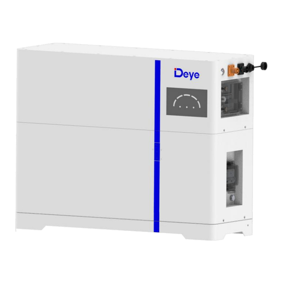
  • Page 5 for communication between multiple parallel batteries. Battery negative The battery system charge and discharge negative port. Battery positive The battery system charge and discharge positive port. BMS Switch BMS Switch: to turn ON/OFF the BMS of the entire battery system. System state indicator Indicates the operating status of the entire battery system, include SOC, RUN, ALARM, and ERROR.
  • Page 6 · BMS function: Protection and Alarm Management and Monitor Charge/Discharge End Intelligent Protect Mode Charge Over Voltage Intelligent Charge Mode Discharge Under Voltage Protect, Charge Current Limit Charge/Discharge Over Current Intelligent Protect Mode High/Low Temperature(cell/BMS) Intelligent Protect Mode Short Circuit Protect 2.2.2 AI-W5.1-PDU1-B Interface 1.LED Status Indicator Instructions...
  • Page 7 SOC LED: 5 blue LEDs, battery capacity indicator, each light represents 20% capacity. Condition ALARM Error LED1 LED 2 LED 3 LED 4 LED 5 Power off Charge Show SOC & highest LED Blink if Alarm blink Exists Discharge or Idle Show SOC &...
  • Page 8 1. Module dock terminals 2. Screw hole 3. System earthing position System earthing position Protective earthing for the battery system connecting to the PE. 2.3 System Technical Data Model AI-W5.1-B combinations Main Parameter Battery Model Number AI-W5.1-B AI-W5.1-B*2 AI-W5.1-B*3 AI-W5.1-B*4 AI-W5.1-B*5 AI-W5.1-B*6 Number of battery units in parallel...
  • Page 9 DC Usable Energy, test conditions: 90% DOD, 0.5C charge & discharge at 25°C. System usable energy may vary due to system configuration parameters. The current is affected by temperature and SOC. Conditions apply, refer to Deye Warranty Letter. Made in China. 2.4 Product application solutions The following illustration shows basic application of this battery.
  • Page 10 3.2 Li-ion Battery Pack packaging box Parts List ~ 10 ~...
  • Page 11 4 Preparations for Installation 4.1 Explanation of Symbol 4.2 Tools These tools are required to install the battery. ~ 11 ~...
  • Page 12 NOTE: Use properly insulated tools to prevent accident tale electric shock or short circuits. If insulated tools are not available, cover the entire exposed metal surfaces of the available tools, except their tips, with electrical tape. 4.3 Safety Gear It is recommended to wear the following safety gear when dealing with the battery pack. 5 Installation instructions 5.1 Installation Precaution Please avoid direct sunlight, rain exposure, snow laying up during installation and...
  • Page 13 Temperature. If the ambient temperature is outside the operating range, the battery pack stops operating to protect itself. The optimal temperature range for the battery pack to operate is 15°C to 35°C. Frequent exposure to harsh temperatures may deteriorate the performance and life of the bat- tery pack.
  • Page 14: Installation Order

    Battery module parallel operation spacing diagram: 5.2.2 Unpacking order First open the box of System Power Distribute Unit, take out the base and handle. The handle is used to carry the battery module, without the handle the battery module will be difficult to re- move from the battery box.
  • Page 15 ii. Open the battery box, take a battery module out. Hold the handle of both batteries with your hands easy for lifting. Put one battery module on the base. Insert the plug on the base into the port on the battery. Pay attention to the direction of the mod- ule to make sure that the blind-mating connectors of the module and the base are at the same side.
  • Page 16 v. After all battery modules are stacked, put the PDU on top of the battery modules. vi.Fix the connection between the battery module and the base, between battery modules, and between PDU and battery module with screws (M4*6). To do this, use a Phillips screwdriver to tighten the screws through the holes on them.
  • Page 17 viii. Set the wall fixing plate (wall part) aside and drill the marked holes. Choose the recom- mend drill head (10mm) to drill 2 holes on the wall,100mm-110mm deep. Put the wall fixing plate (wall part) in front of the holes, then insert the expansion screw of M6*100 and tighten.
  • Page 18 Step 2 Fix the height of the expansion frame with screws(M8*70). The distance between the holes of the retractable support is 25mm. The maximum length of the retractable bracket is 605mm and the minimum length is 305mm. Retractable legs (dashed frame) are optional and can be added according to demand. Step 3 Stack battery packs to complete the installation And make sure the wall fixing plate is attached to the wall.
  • Page 19 5.3 Grounding description Use a torque wrench to unfasten the M4 screws on the base and remove the ground wire (the yellow and green wire as shown in Section 3.1) from the accessory bag. Lock M4 screws and install the product ground point (as shown in the following figure). Install the other end according to local regulations.
  • Page 20 5.4 Electrical Connection 5.4.1 Battery System (It is suitable for scenarios where the inverter power ≤ Single 12kW) CAUTION It should be noted that the maximum current of single battery system is 250A (inverter power must not exceed 12kW), exceeding 250A will cause heating of the connectors and cable, and in severe cases, it will cause a fire accident.
  • Page 21 or larger capacity systems: 5.5 Method of monitoring parallel units Parallel connection: ~ 21 ~...
  • Page 22 Two batteries are connected in parallel, with one end connected to the positive and negative poles of the other battery pack, the positive pole connected to the positive pole, and the negative pole connected to the negative pole. A network cable is used to connect the OUT communication interface of one battery pack, and the other end connected to the IN communication port of the other battery pack.
  • Page 23 5.6 Visual Inspection of the Connection After connecting the battery, check for: Use positive and negative cables correctly.  Connection of the positive and negative terminals.  All the bolts are tightened.  Cables fixation and the appearance.  The installation of the protecting cover. ...
  • Page 24 Power down steps: ① Turn off the PCS switch. ② Press the battery module button. ③Turn off PDU power circuit breaker. ④ Turn off the battery module circuit breaker. ⑤Complete shutdown. ~ 24 ~...
  • Page 25 6 Inspection, Cleaning and Maintenance 6.1 General Information The battery product is not fully charged. It is recommended that the installation be com-  pleted within 3 months after arrival; During the maintenance process, do not re-install the battery in the battery product. Oth- ...
  • Page 26: Maintenance

    Regularly check the battery’s state of charge. Lithium Iron Phosphate batteries will slowly  self-discharge when not in use or whilst in storage. Consider replacing the battery with a new one if you note either of the following condi-  tions: - The battery run time drops below 70% of the original run time.
  • Page 27: Overvoltage Protection

    The cell temperature sensor has failed. Due to large self- discharge, the cell over discharges to below 2.0V after long term Electrochemical The voltage of the cell Replace the storage. cell fault is low or unbalanced. battery. The cell is damaged by external factors, and short circuits, pinpricks, or crushing occur.
  • Page 28 8.1 Recovery process and steps of cathode materials Aluminum foil as collector is amphoteric metal. Firstly, it is dissolved in NaOH alkali solution to make aluminum enter the solution in the form of NaAlO . After filtration, the filtrate is neutralized with sulfuric acid solution and precipitated to obtain Al (OH) .
  • Page 29 Figure 9-1: Class 9 Miscellaneous Dangerous Goods and UN Identification Label 10 Compatible with inverter type lnverter model : SUN-3K-SG03LP1-EU  SUN-3.6K-SG03LP1-EU  SUN-5K-SG03LP1-EU  SUN-6K-SG03LP1-EU  SUN-5KSG04LP3-EU  SUN-6KSG04LP3-EU  SUN-8KSG04LP3-EU  SUN-10KSG04LP3-EU  SUN-12KSG04LP3-EU  ~ 29 ~...

This manual is also suitable for:

Ai-w5.1-b